
Troubleshooting guide

MAGNUM VERSION 8 MANUAL REVISION 3.1
161
# Name Description
CLLC LEVEL TRG
(Only CENT)
The ‘Value’ is the target that is to be maintained of the condenser liquid level.
The ‘Time(sec)’ contains the dead band of the target. For example if the value is 60.0 (target)
and the ‘Time(sec)’ field is 5 (dead band) the control zone for the condenser liquid level is
between 55.0 and 65.0.
217 CLLC VALVE TRG
(Only CENT)
The ‘Value’ is the target or minimum opening of the CLLC control valve.
The ‘Time(sec)’ contains the normal delay between making valve adjustments. This time is
expressed in seconds.
The ‘Sec. to Ignore Safety’ contains the delay between making valve adjustments when the
CLLC is in a startup mode or the chilled water is not with in its control zone, this is an
unstable condition.
The ‘Window to extend Safety Time(sec)’ contains the maximum valve adjustment value.
This value has an assumed decimal place; that is a value of 50 will allow a maximum
adjustment of 5.0. The actual adjustment will be calculated based upon the valve setting
and its desired position.
This set point is only used if the AO TYPE of CLLC valve has been selected.
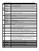
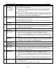
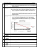
LOW EXV TARGET
(Only HVAC)
The minimum Refrigerant Level target. If active and the EXV is controlled by Refrigerant
Level, then a new variable level target logic will be activated. As the unit capacity
increases, the refrigerant level target will change according to a linear calculation
between Setpoint #9 “LEVEL TARGET” (the maximum target level) and Setpoint #217
“LOW EXV TARGET” (the minimum target level). This relationship is explained in the
following graph:
218 CLLC MAX ROC
(Only CENT)
The ‘Value’ contains the rate of change that will determine if the condenser liquid level rate of
change is moving fast enough.
OIL REC VENT
CYCLE #1
Time on for device #1vent cycle.
219 OIL REC VENT
CYCLE #2
Time on for device #2 vent cycle.
220 OIL REC VENT
CYCLE #3
Time on for device #3 vent cycle.
221 OIL REC VENT
CYCLE #4
Time on for device #4 vent cycle.
222 OIL REC OIL POT
CYCLE
Time on for oil pot cycle, common.
223 OIL REC OIL
CHARGE
CYCLE
Time on for oil charge cycle.
224 OIL REC REPEAT
CYCLE
Time delay before repeating cycles.
20%
25%
30%
35%
40%
45%
50%
25% 80% 135% 190% 245% 300%
EXVLevelTarget
EXVLevel
Target
(Number of steps
(3) × Setpoint #30
"MAX FLA %")
Setpoint #31
"MIN FLA%"
Calculated EXV Level Target
Total Cooling Capacity of Unit
(Example of a 3 step system)
Setpoint #9
“LEVEL TARGET”
Setpoint #217
“LOW EXV TARGET”