
Troubleshooting guide


MAGNUM VERSION 8 MANUAL REVISION 3.1
142
13.2. Setpoints for Magnum HVAC and CENT V8 Software
If a particular Setpoint is supported only in either HVAC or CENT software it will be indicated with (Only HVAC) or
(Only CENT).
# Name Description
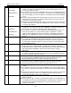
1 CTL TARGET
Control target. This value is used as the base to develop the Control Zone. Refer to Setpoints
#2 and #3.
The control target is used with the control zone and rate of change of the controlling sensor to
determine required action for the Magnum. The controlling sensor is usually one of the
following:
Leaving Temperature – Most common used as a target, fitting for most applications.
Return Temperature – Used in sites with large air masses, ice rinks, common areas, etc.
Suction Pressure – Used in continuously running process systems.
2 CTL ZONE + Added to the CTL TARGET to create the upper limit of the control zone.
STAGE CUT OUT
(Cut In/Out Control)
Offset used in calculating the cut out value. Subtracted from the stage cut in Setpoints #3
through #18
3 CTL ZONE - Subtracted from the CTL TARGET to create the lower limit of the control zone.
(Only CENT) If this Setpoint is a target type and the Low Zone cell is >0 and <=5, use this value as the
offset to the target to allow an unload adjustment of 3 else use 1.
STAGE 1 CUT IN
(Cut In/Out Control)
Stage 1 cut in, Setpoint value contains the voltage when this stage is turned on.
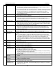
4 HGS TEMP ON
This Setpoint is used with screw compressors with a hot gas bypass solenoid. When this
Setpoint is active and the control temperature is less than the CTL TARGET plus the
value in this Setpoint and the FLA % is within 25% of Setpoint #31 “MIN SLIDE%”, the
hot gas bypass solenoid for the compressor will be turned on.
‘Time (sec)’ field: Contains the minimum slide percentage offset to enable the HGB. If non-
zero, this value is added to Setpoint #31 “MIN FLA%” to determine the range in which to
enable the HGB. If zero, then the default value of 25 is added. For example, if this value
is 10, then the HGB will enable when the compressors FLA% is within 10% of Setpoint
#31 “MIN FLA%”.
STAGE 2 CUT IN
(Cut In/Out Control)
Stage 2 cut in, Setpoint value contains the voltage when this stage is turned on.
5 HGS TEMP OFF
This Setpoint is used with screw compressors with a hot gas bypass solenoid. When this
Setpoint is active and the control temperature is greater than the CTL TARGET plus the
value in this Setpoint or the FLA % is not within 25% of Setpoint #31 “MIN SLIDE%”, the
hot gas bypass solenoid for the compressor will be turned off.
‘Time (sec)’ field: Contains the minimum slide percentage offset to disable the HGB. If non-
zero, this value is added to Setpoint #31 “MIN FLA%” to determine the value at which to
disable the HGB. If zero, then the default value of 30 is added. For example, if this value
is 15, then the HGB will disable when the compressors FLA% is 15% or more above
Setpoint #31 “MIN FLA%”.
STAGE 3 CUT IN
(Cut In/Out Control)
Stage 3 cut in, Setpoint value contains the voltage when this stage is turned on.
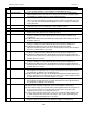
6 HGS PSI ON
This Setpoint is used with screw compressors with a hot gas bypass solenoid. When this
Setpoint is active and the suction pressure is less than the value of this Setpoint and the
FLA % is within 25% of the Setpoint #31 “MIN SLIDE%”, the hot gas bypass solenoid for
the compressor will be turned on.
STAGE 4 CUT IN
(Cut In/Out Control)
Stage 4 cut in, Setpoint value contains the voltage when this stage is turned on.
7 HGS PSI OFF
This Setpoint is used with screw compressors with a hot gas bypass solenoid. When this
Setpoint is active and the suction pressure is greater than the value of this Setpoint or the
FLA % is not within 25% of the Setpoint #31 “MIN SLIDE%”, the hot gas bypass solenoid
for the compressor will be turned off.
STAGE 5 CUT IN
(Cut In/Out Control)
Stage 5 cut in, Setpoint value contains the voltage when this stage is turned on.