
Troubleshooting guide


MAGNUM VERSION 8 MANUAL REVISION 3.1
10
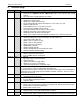
Setpoint #35 “AMP DB LO”
Setpoint #36 “AMP DB HI”
Setpoint #125” Eco StageDly”
Setpoint #143 “UNLOADED %”
Updated 7.4.1. Screw Compressor with Slide Piston
Updated 7.75. HVAC Defrost Cycle
10-18-13 MAS
REV 3.1
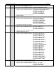
Updated section 13.2 Magnum Setpoints - Setpoint #38 “UNLOAD PULSE”
Setpoint #167 “PURGE FLT ERROR”
Setpoint #168 “PURGE COUNT”
Setpoint #170 “EXCESS PURGE”
Setpoint #229 “CHK VALVE FLT”
Setpoint #230 “MAX DIFF PSI ROC”
Added 7.10 Custom Rotation
Added Setpoint #228 “FORCE ON OIL RECOVERY”
3. Introduction to Magnum V8 Software
Magnum V8 software has been designed to control many different types of compressors of both fixed and
variable capacity, as well as many additional features. Supported control options include multiple liquid line
solenoids, electronic expansion valves (EXVs), liquid injection, economizers, hot gas bypass, variable
frequency drives for compressors (VFDs), digital scrolls, and many more.
Applications vary from control of a single compressor to complex multiple compressor systems. In all
applications, however, safety and operating efficiency is of primary importance. The controller interface is made
to be informative and meaningful, with built-in logic to prevent unsafe conditions from occurring. This helps
reduce or even completely eliminate nuisance alarms.
There are two types of Magnum software described in this manual:
HVAC V8- This software supports all types of compressors except centrifugals. It supports the configuration
type 106 Chiller V8 CFG, as well as 109 Loop Control CFG. If this software is loaded into a Magnum with a
different type of configuration file, an invalid configuration type message will be generated.
CENT V8- This software supports only centrifugal compressors, and requires a configuration type 119 CENT
MAG CFG. If this software is loaded into a Magnum with a different type of configuration file, an invalid
configuration type message will be generated.
These software types are very similar and most topics will apply to both. However, if a topic applies only to one
type it will be labeled as either ‘only HVAC’ or ‘only CENT’.
3.1. Magnum V8 Software Control Point Capacity
Circuits (compressors) up to 20
Steps per Compressor up to 4
Relay Outputs up to 80
Analog Outputs up to 20
Sensor Inputs up to 80
Setpoints 230
Alarms 100
3.2. Magnum Hardware Supported by Magnum V8 Software
The following MCS boards can be connected together through the MCS-I/O communications terminal
block:
MCS-Magnum (10 RO’s, 12 SI’s, 4 Digital SI’s, and 4 AO’s)
MCS-I/O (8 RO - 8 SI - 1 AO with I/O 7.00-C with a GAL 5.0 chip)
MCS-RO8 (8 RO)
MCS-SI16 (16 SI)
MCS-RO10 (10 RO)