
Data Sheet
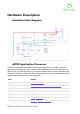
Table Of Contents

Debugging
The interface processor can be used with special host tools to debug code that is running
on the application processor. It connects to the application processor via 4 signal wires.
The KL27 interface processor code can also be debuged via it’s integral SWD software
debug interface, for example to load initial bootloader code into this processor at
manufacturing time, or to recover a lost bootloader.!
Mechanical
We have some$nice 2D and 3D CAD drawings and models of the micro:bit$including all
the important dimensions. These models can be used as a basis for generating really nice
marketing and project images of the micro:bit, but also as a basis for accurate
manufacture of attachments e.g. via 3D printing.!
$
Communications Device Class (CDC)
More Info
DAPLink
item
details
item
details
Protocol
CMSIS-DAP
Options
JLink/OB (via different firmware)
More Info
Mbed debugging micro:bit
item
details
Dimensions
51.60mm(w) 42.00mm(h) 11.65mm(d), button depth to board
4.55mm, speaker depth to board 3.00mm, JST connector to
board 5.50mm
Weight
TBC
10
© Micro:bit Educational Foundation 2020