
Specifications


7
Unit Operation
1. Turn the blower on. This action will cause the
fi lter unit to activate and start cleaning fi lters.
NOTE: Some particulate may pass through the
cartridge fi lters and blower upon initial start-up.
This will end once the fi lters have been seasoned
and a power cake has formed on the fi lter. If this
condition continues to occur, refer to the section
“Roto-Pulse Cleaning Timer Adjustments” to
increase the period of time between pulses.
2. once the unit is running the Roto-Pulse cleaning
system will be operational. Operation is
detected by hearing a .07-second air pulse
approximately every 5 seconds. If adjustment
to timing of pulses is desired refer to the secion
“Roto-Pulse Cleaning Timer Adjustments”.
3. Check the After-Pulse Cleaning cycle by turning
off the unit via the stop switch located on the
side of the electrical box. The unit should
continue to pulse every 5 seconds for a period
of approximately 17 minutes. If adjustment
to the after-pulse time is desired, refer to the
section labeled “After-Pulse Cleaning”.
Cartridge Cleaning Operation
The Micro Air Dust Collector is designed with the
Roto-Pulse Cleaning System to clean the cartridge
fi lters.
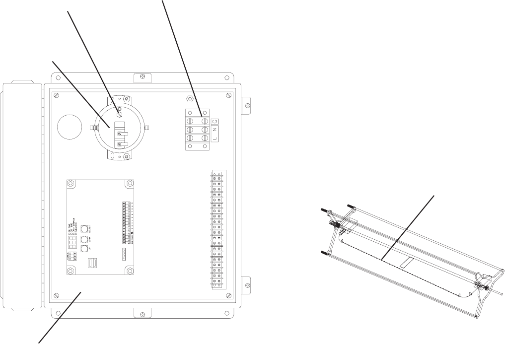
This system provide superior cleaning performance
using a rotating tube with pre-drilled holes (see
Figure 8). As the diaphragm valve opens, the Roto-
Pulse tube rotates while air exits the holes, thus
providing the cleaning of the cartridge.
Electrical Installation
NOTE: All electrical work must be done by a
qualifi ed electrician.
CAUTION: Installation can cuase exposure to
live components. Disconnect electrical power
befor proceeding with installation. Proper lock
out/tag out procedures should be used.
1. Open the electrical box cover located on the
side of the unit. Make connections from your
120V supply power to terminal L, N and G (see
fi gure 7).
2. When supply power has been terminated,
reconnect the power. Momentarily turn the
remote blower on and adjust pressure switch
via set screw until contact is made. Use ohm
meter to measure continuity across the pressure
switch.
FIGURE 7
SET SCREW
POWER
CONNECTION
PRESSURE
SWITCH
TIMER
BOARD
FIGURE 8
ROTO-PULSE TUBE