
Specifications


5
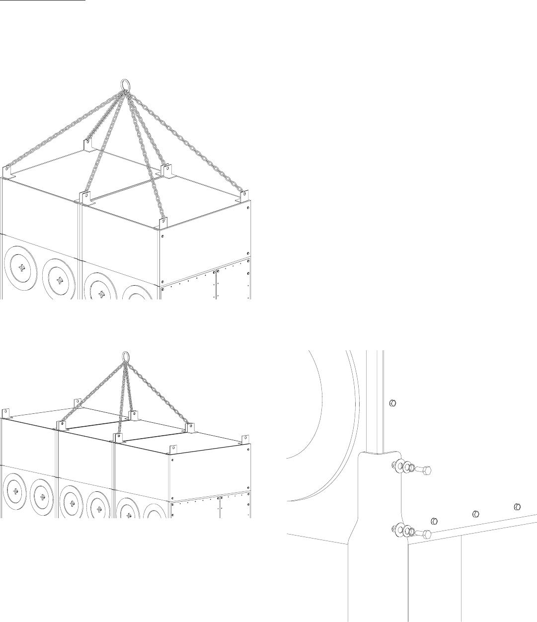
FIGURE 2
FIGURE 1
Assembly of Unit:
1. Determine the location where the unit is to be
installed. Be sure to allow suffi cient room to
access the unit for servicing and maintenance on
all sides.
2. Lift the unit with a lift truck or overhead crane
using the four lifting lugs located at the corners
of the unit (see Figure 1 & 2).
3. Bolt on each of the legs. The two lower bolts at
each corner will be removed and used to attach
each corner leg (see Figure 3). Attach middle
legs with provided hardware (see Figure 4).
4. When the legs have been completely installed
each leg should be bolted to the ground suing
the hole provided in the base plate of the leg
(see Figure 5).
5. After the legs have been properly anchored, the
dust containment system can be installed.
CAUTION: THE UNIT IS NOT DESIGNED
TO BE OPERATED WHILE HANGING FROM
LIFTING BRACKETS. UNIT MUST BE
MOUNTED ON LEGS AND CROSS BRACING
INSTALLED.
CAUTION: THE UNIT SHOULD BE LIFTED
OFF THE SKID AND SET INTO POSITION
BY UTILIZING THE LIFTING LUGS
PROVIDED. SEVER DAMAGE MAY RESULT
FROM ANY OTHER LIFTING METHOD.
FIGURE 3