MICRO-AIR DUST COLLECTOR Installation and Operation Manual MODEL RP6-2, RP-3, RP8-2 & RP-3 Important: This manual contains specific cautionary statements relative to worker safety. Read this manual thoroughly and follow as directed. It is impossible to list all the hazards of dust control equipment. It is important that use of the equipment be discussed with a Micro Air Representative. Persons involved with the equipment or systems should be instructed to operate in a safe manner.
TABLE OF CONTENTS CAUTIONS 3 SPECIFICATIONS 4 INSTALLATION INSPECTION EQUIPMENT / TOOLS REQUIRED ASSEMBLY OF UNIT COMPRESSED AIR INTALLATION ELECTRICAL INSTALLATION UNITS INSTALLED OUTDOORS UNIT OPERATION CARTRIDGE CLEANING OPERATION ROTO-PULSE CLEANING TIMER ADJUSTMENTS AFTER-PULSE CLEANING TIMER ADJUSTMENTS 5 5 5 6 7 7 7 7 8 8 OPTIONAL COMPONENT INSTALLATION DUST COLLECTION TRAY INSTALLATION PROCEDURE DUST COLLECTION HOPPER INSTALLATION PROCEDURE DUST COLLECTOR LEG BRACING INSTALLATION PROCEDURE MAG
All wiring must be done in accordance with applicable National, State, and local electrical code. MicroAir does not determine what is acceptable in any local jurisdiction and cannot be held responsible for wiring that does not meet local codes. Cautions: Avoid mixing combustible materials, such as buffing lint, paper, wood, aluminum, and magnesium dust, and with dust generated from grinding ferrous metals due to the potential fire hazard caused by sparks in the dust collector.
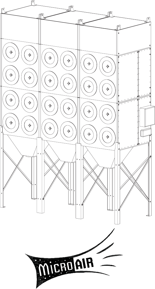
Specifications: RP6-2 & RP8-2: 2 ea. Cust Collection Tray/Hopper 6 ea. Mounting Legs Input Voltage: 120 Volt Cabinet Dimensions: RP6-2 RP6-3 RP8-2 RP8-3 RP6-3 & RP8-3: 3 ea. Cust Collection Tray/Hopper 8 ea. Mounting Legs 151” H x 84” W x 56” D 151” H x 126” W x 56” D 173” H x 84” W x 56” D 173” H x 126” W x 56” D Weight: RP6-2 RP6-3 RP8-2 RP8-3 2318 lb. 3477 lb. 3098 lb. 4647 lb.
2. Lift the unit with a lift truck or overhead crane using the four lifting lugs located at the corners of the unit (see Figure 1 & 2). Assembly of Unit: 1. Determine the location where the unit is to be installed. Be sure to allow sufficient room to access the unit for servicing and maintenance on all sides. 3. Bolt on each of the legs. The two lower bolts at each corner will be removed and used to attach each corner leg (see Figure 3). Attach middle legs with provided hardware (see Figure 4). 4.
FIGURE 4 MIDDLE LEG 1/2” DIA. HOLES COMPRESSED AIR INLET 3/4” FEMALE NPT BASE PLATE FIGURE 5 Compressed Air Installation The compressed air inlet for the Roto-Pulse cleaning system is at the top of the piping assembly located on the backside of the unit (see Figure 6). A minimum of a 3/4 inch line and plant air at a pressure at 80 psi is required for proper operation of the Roto-Pulse cleaning system. A single 3/4” air line, branched to each manifold, is sufficient to the entire unit.
Electrical Installation Unit Operation 1. Turn the blower on. This action will cause the filter unit to activate and start cleaning filters. NOTE: All electrical work must be done by a qualified electrician. NOTE: Some particulate may pass through the cartridge filters and blower upon initial start-up. This will end once the filters have been seasoned and a power cake has formed on the filter.
differential across the filters. If you can not maintain this minimum level of differential across the filters the time between cleaning pulses should be increased until this can be achieved. 1. For proper cleaning, the compressed air pressure should be regulated at 80 psi maximum. 2. During normal operation the Roto-Pulse cleaning system is factory set to clean two (2) cartridge filters for a period of .07 seconds every 5 seconds. 3.
RP DUST COLLECTOR DUST COLLECTION TRAY INSTALLATION PROCEDURE Each Kit Includes: 20 ea. 12 ft. 86 in. 1 ea. 2 ea. 1 ea. 2 ea. P3543 P3686 P1367 38379-01 38380-01 38378-01 P1372 Self-Tapping Screws 3/16” x 1” Self-Adhesive Foam 1” x 3/4” Foam (Placed at inside of Access Door) Dust Tray Weldment Dust Tray Dust Tray Access Door Door Latch NOTE: Dust tray access door must be removed prior to assembly INSTALLATION: 1. Apply self-adhesive foam to the bolt hole flange on the dust tray. 2.
RP DUST COLLECTOR DUST COLLECTION HOPPER INSTALLATION PROCEDURE Each Kit Includes: 20 ea. 12 ft. 1 ea. P3543 P3686 38222-01 Self-Tapping Screws 3/16” x 1” Self-Adhesive Foam Hopper Weldment INSTALLATION: 1. Apply self-adhesive foam to the bolt hole flange on the hopper. 2. Align the hole pattern on the hopper flanges with the hole pattern on the underside ot the unit. 3. Attach the hopper (38222-01), usting twenty (20) self-tapping screws, to the unit.
RP DUST COLLECTOR DUST COLLECTOR LEG BRACING INSTALLATION PROCEDURE Each Kit Includes: 15 ea. 15 ea. 30 ea. 30 ea. 2 ea. 4 ea. P222 P2614 P3615 P249 38394-01 38394-02 5/16” Hex Nuts 5/16” Hex Bolts 5/16” Flat Washers 5/16” Lock Washers Short Leg Cross Brace Long Leg Cross Brace INSTALLATION: 1. Straighten and plumb each individual leg. 2. Bolt each end of the cross braces to the legs. 3. Tighten all bolts until secure.
RP DUST COLLECTOR AFTERMARKET MAGNEHELIC KIT INSTALLATION PROCEDURE This Kit Includes: 1 ea. 1 ea. 2 ea. 4 ea. 10 ft. 38294-01 P3755 P2098 P3543 P1848 Magnehelic Mounting Bracket 0-10” w.c. Magnehelic Gauge 1/8” Male x 1/4” Barb Fitting 1/4”-14 x 1 Self-taping Screw 1/4” Clear Tubing INSTALLATION: 1. Remove parts from package and inspect for any possible damage incurred during shipping. 2. Turn off dust collector and disconnect power to the unit. 3.
RP DUST COLLECTOR PHOTOHELIC KIT INSTALLATION PROCEDURE This Kit Includes: 1 ea. 1 ea. 2 ea. 4 ea. 10 ft. 38293-01 P3643 P2098 P3543 P1848 Photohelic Mounting Bracket 0-10” w.c. Photohelic Gauge 1/8” Male x 1/4” Barb Fitting 1/4”-14 x 1 Self-taping Screw 1/4” Clear Tubing NOTE: When using a Photohelic on a dust collector installed outdoors, the gauge can not be mounted on the unit. It must be mounted indoors. The gauge is not rated for outdoor use. INSTALLATION: 1.
RP DUST COLLECTOR BARREL LID KIT INSTALLATION PROCEDURE Each Kit Includes: 1 ea. 1 ea. 4 ea. 38198-01 P3966 P3119 Adapet Plate Barrel Lid and Duct Kit 3/8-16 x 1” Hex Head Bolt 8 ea. P2206 4 ea. P141 4 ea. P142 Flat Washer 3/8-16 Nut Lock Washer INSTALLATION: 1. Remove parts from box and inspect for any possible damage incurred during shipping. 2. Bolt Adapter Plate and Hopper Adapter to the Hopper using the 3/8” hardware. 3. Clamp the Pipe Section to the Barrel Lid.. 4.
RP DUST COLLECTOR TOP MOUNTED BOLWER INSTALLATION PROCEDURE This Kit Includes: 12 ea. 12 ea. 12 ea. P142 P2206 P3119 3/8” Split-lock Washers 3/8” Flat Washers 3/8” - 16 x 1” Hex Head Bolts Equipment Required: Chain Lift Truck or Crane 9/16” Wrench INSTALLATION: 1. Remove parts from the cloth bag. 2. Turn off dust collector and disconnect power to the unit. 3. Carefully lift the blower and position it over the adapter plate. 4. Align and lower the blower to the top of the adapter plate. 5.
RP6-2 WIRING DIAGRAM FIGURE 16 16
RP6-3 WIRING DIAGRAM FIGURE 17 17
RP8-2 WIRING DIAGRAM FIGURE 18 18
RP8-3 WIRING DIAGRAM FIGURE 19 19
RP PARTS LIST - CABINET FIGURE 20 ITEM PART NO. DESCRIPTION ITEM PART NO. DESCRIPTION 1 36720-11 Filter Support Assembly (Roto-Pulse) 16 P3734 1/4” O.D. Air Hose 2 P3649 4-Prong Knob 17 P3744 12 Pilot Valve Enclosure 3 39034-01 End Cap Assy. (Including Door Seal) N.S. P3657 8 Pilot Valve Enclosure 4 38342-01 Door Seal N.S. P3656 6 Pilot Valve Enclosure P7400RM 80/20 Cellulose Cartridge Filter 250sf N.S.
FIGURE 21 FIGURE 22 21
Notes: Date of Install: ________________________________________________________ Installer: ________________________________________________________ ______________________________________________________________________________________ ______________________________________________________________________________________ ______________________________________________________________________________________ ______________________________________________________________________________________ __________