
EasyTouch RV 359 Manual

5
©2022 Micro-Air Corp May 20, 2022, revision 1.3
Wiring the thermostat
SAFETY FIRST: Turn off power to the air conditioner breaker and to the 12-volt circuit powering
the thermostat. There is always a risk of shock in any system that is connected to high voltage utility power
so removing power greatly reduces that risk and the risk of shorts that can damage something.
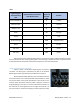
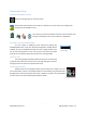
Use the table entries written in Table 1 to complete the wiring. Insert each wire as described in the section
titled “Using the push button terminals”. Insert the +7.5-volt wire last so it cannot contact any other wires
when the tape is removed.
Change the control box wiring
SAFETY FIRST: Remove power before changing the
control box wiring.
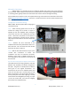
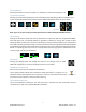
Step 1: After removing power from the AC unit,
remove the ceiling vent as shown in Figure 2.
Identify the red and red/white wires exiting the
control box near the area indicated by the blue
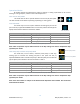
arrow. These wires are pulled out and shown in
Figure 3 connected to a brown and thin red wire.
They may still have labels on them to indicate their
function.
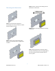
Step 2: Remove the wire connected to the
red/white wire which may still have the label “To T-
Stat 7.5 Screw”. Put a connector over the red wire
with stripe as shown in Figure 3.
Step 3: Add the wire disconnected in step 2 to the
+12-volt wire connections as shown. This
installation uses wire nut electrical connectors.
However, crimp splice or WAGO connectors are
more desirable for the vibrations encountered by
the terminals.
My wire colors and gauges are different than shown?
There will be 4 wires of varying thickness and color
between red, red/white, and brown, configured in
two pairs. The goal is to identify which of these 4
wires goes to the original thermostat’s +7.5
terminal (one of the red or red/white wires) and
move it to the other pair. This will route 12 volts
down to EasyTouch. You should have ultimately a
wire by itself (the control box outgoing +7.5 wire)
and the other three altogether (incoming +12, input
+12 for the control box, and now the outgoing
thermostat red or red/white wire).
Figure 3
Figure 2