EasyTouch 359 Operating Manual Revision 1.3 1 ©2022 Micro-Air Corp May 20, 2022, revision 1.
Table of Contents Safety First .................................................................................................................................................... 3 Installing the thermostat .............................................................................................................................. 3 Removing the old thermostat ...................................................................................................................
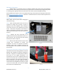
The EasyTouch 359 model 12-volt thermostats were designed to directly replace Dometic™ model 3106995 single zone DC 7.5-volt thermostats. The thermostats can be used in other applications with certain electrical limitations as explained later in this document. Safety First Turn off power to the air conditioner breaker and to the 12-volt circuit powering the thermostat. There is always a risk of shock in any system that is connected to high voltage utility power so removing power greatly reduces that risk.
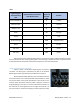
Table 1 Connect to EasyTouch terminal label Function Red or Red/White R +7.5VDC Black or Green B -Ground Orange or Tan GL Fan Green GH Fan high Yellow Y Cool Violet or Orange WHP HP (heat pump) White W Furnace Not used SEN Sensor Not used SEN Sensor Typical original thermostat wire color Original factory wire harness color (Write in here) Disconnect the red or red/white wire labeled +7.5V and place a piece of tape around the exposed wire end.
Wiring the thermostat SAFETY FIRST: Turn off power to the air conditioner breaker and to the 12-volt circuit powering the thermostat. There is always a risk of shock in any system that is connected to high voltage utility power so removing power greatly reduces that risk and the risk of shorts that can damage something. Use the table entries written in Table 1 to complete the wiring. Insert each wire as described in the section titled “Using the push button terminals”. Insert the +7.
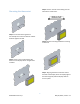
Step 3: Screw in second screw making sure the two buttons remain level. Mounting the thermostat Step 1: Locate the mounting buttons horizontally across the hole with the smaller diameter against the wall. Step 4: Remove mounting tab before mounting on the wall. Step 2: Screw in one screw and level the buttons so the display will be straight when installed. Step 5: Aligning the buttons with the holes in the back of the display.
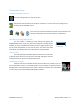
Thermostat Setup Setting the Available Sources Press the settings button on the main screen. Use the back and next buttons to locate the “switches” icon. Press the icon to configure the modes from the available sources. Press the icons to select or deselect the mode. A red circle with a line through it will appear over the source when it is deselected. Gas Heat Override Enable/Disable You can enable or disable gas heat override by tapping the Enable/Disable button under the “Auto Gas Changeover” heading.
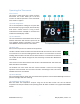
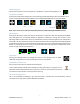
Operating the Thermostat Main Screen This screen is where most time is spent using the thermostat. This screen allows you to set and monitor the desired operation of the thermostat and is shown in Figure 4. (1) Inside temperature This is the temperature reading for the space that the thermostat is trying to temper, determined by a local sensor. “Inside” means it is using a sensor inside the thermostat. “Inside(R)” is not used in this model and should display “Inside”.
(6) System Power Use the power button to turn the system on or off. Button is red for off and green for on. Power (7) Operational Mode Pressing the mode button changes the current operating mode depending on what is available in your system. All possible modes are listed below. See the Operational Modes section for more details.
Operational Modes All modes operate the overhead fan and/or a heating or cooling cycle based on the current heating or cooling setpoint, relative to the inside temperature. Fans and Fan Only Mode This mode lets the fan to operate based on the chosen (8) Fan Speed. This will circulate the air without operating any heating or cooling cycles. Fan Speed Fan Only Mode Cool Only Mode This mode only runs a cool cycle to maintain the cooling set-point in the space.
Furnace Only or Aqua Only Mode Aqua Only Mode This mode only runs an auxiliary heating cycle to maintain the heating setpoint in the space. Set the (7) Operational Mode button to Furnace Only or Aqua Only and the desired (8) Fan Speed, where behavior will then be based on Table 4. See section Furnace/Aqua Icons for details on the auxiliary heating icon.
Gas Heat Override Note: See section Gas Heat Override Enable/Disable for enabling and disabling this feature. Gas Heat Override operation is an algorithm for calling for additional stages of heat when the thermostat determines more are needed. The two escalating stages are shown in Table 5. This logic is disabled when both stages are not available.
Local Weather and Local Time Local weather is displayed on the main screen and shown visibly in section (2) Local Weather under section Main Screen. Tapping the button will reveal more detailed weather information of the last received weather data. The local temperature is displayed in the lower left corner of the main screen, as shown in section (11) Outside Temperature. A valid location and an internet connection on the thermostat are required to retrieve weather data.
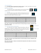
Schedule Screens The schedule supports 7 day per week scheduling of events. Events can include changes to the set point or mode of operation for one or more zones. Figure 6 shows the main schedule screen. The smart device application also offers a method to copy days. Once a schedule is set for one day, it can be copied to any other day. (1) Day of the Week Day of the week is selected from the days along the top of the screen. The day selected appears in white.
Figure 7 shows the edit screen when an event is tapped as shown in (2) Scheduled Events on the main schedule screen. The event on the main screen and action time in the edit screen will show disabled until a time is set. Press “Disabled” (1) at the top of the screen to show a gray box around the disabled selection. Use the up and down arrows to make a change. The up and down arrows change to full color once a selection is made. Use the back arrow (2) to save any changes and leave the screen.
Settings Screens The settings screens allow for further configuration and control of the thermostat. It is a paged system that you can navigate through to see all available settings. Each setting button can be tapped to configure the related settings. Note: Not all settings may be available based on your EasyTouch RV model. If you do not see the graphic then it is not available for your system. Settings Button Tap the settings button as shown in section (9) Settings under Main Screen to view them.
Bluetooth (Account) Password Reset This screen is used to reset the saved Bluetooth password in the thermostat. This is the password that must match your EasyTouch RV app account to make remote connections. Only one account can have access to the thermostat. Use this whenever you reset the Bluetooth Password Reset password to your app account to regain remote access to the thermostat. Temperature Reading Adjustment This setting allows you to calibrate the Inside temperature reading with an offset.
Touchscreen Calibration The EasyTouch RV touchscreen is calibrated at the factory to accurately interpret your touch presses. Pressing the Touchscreen Calibrate Button will allow you to recalibrate the touch press area. Follow the on-screen prompts to calibrate the touchscreen. Any overlapping test targets on the second screen is a good calibration. Touchscreen Calibrate Button Restart This setting will turn the thermostat off then on as if removing and restoring power.
Smart device settings options Reset device This Bluetooth only feature allows resetting the display just as if you removed and restored power. Calibrate Touchscreen It is normally not necessary to recalibrate the touchscreen. This selection prompts the user to press the four corners of the display then test the calibration using three diagonal marks. This feature is only available from Bluetooth as being at the thermostat is required.
Troubleshooting The most common problems during installation are mismatching the wires and not seating the wires in the connector properly. The first step should always be to recheck the instructions and make sure the wires are seated properly. The second most common problem is not knowing the thermostat operation. If the system is running a heating or cooling cycle, the large numbers of the temperature set point will turn red for heating and blue for cooling.
Working Wirelessly This thermostat may be operated remotely using either Bluetooth or Wi-Fi. All connectivity is performed through the EasyTouch RV App on a smart-device. The app is downloaded from the Google Play store or Apple App store. The first time the app is opened, it will ask to create an account. Create your account and follow the prompts to connect your thermostat. EasyTouch RV App icon Bluetooth is a limited range method to connect, typically used when near the thermostat.
Connecting to a New Wi-Fi Network You can connect to the thermostat from anywhere using the app when the thermostat is connected to an internet source. The internet source must be a 2.4GHz network to connect to EasyTouch. 1. Connect to the thermostat in Bluetooth (Apple) and press the settings gear. 2. Select Wi-Fi Setup from the settings window. 3. Connect to a network: a. The SSID (network name) will say “searching” then switch to “select”. Tap “select” to choose from a network the thermostat can hear. i.
Appendix Using this thermostat on other applications It is possible to use this thermostat for custom installations. The outputs are all pull to ground active and pullup to “12 VDC” inactive outputs. Maximum drive current is 200mA per output. This thermostat cannot be used for 24 VAC applications. Contact Micro-Air if you are not certain this device will work in your intended application. 23 ©2022 Micro-Air Corp May 20, 2022, revision 1.