EasyTouch 352 and 352C Operating Manual Revision 1.
Contents Installing the thermostat .............................................................................................................................. 4 Removing the old thermostat ................................................................................................................... 4 Using the push button terminals .............................................................................................................. 4 Wiring the thermostat ...................................
Connecting to a new WIFI network ........................................................................................................ 16 Updating the thermostat ........................................................................................................................ 16 3 ©2021 Micro-Air Corp May 20, 2021, revision 1.
The EasyTouch 352 model thermostats were designed to directly replace Coleman™, Airxcel™ and RVP™ single zone DC thermostats. The thermostats can be used in other applications with certain electrical limitations as explained later in this document. Installing the thermostat There are three steps to installing the thermostat. First remove your old thermostat. Next disconnect and reconnect the wiring. Finally install the mounting pins to the wall and mount your new thermostat.
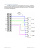
Wiring the thermostat Original thermostats can have a plug-in connector, push button connector block, or be direct wired to the RV manufacturers wiring. All EasyTouch versions of the 352 thermostats have the push button connector block. 352C models (X03 and X04 extensions) have a connector pre-wired to the connector block for those models that come with connectors. The tables in each section below list the RVP/Airxcel/Coleman thermostat model numbers that can be used with each thermostat installation type.
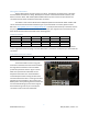
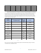
Direct wired models 7330*332* 7330*335* 7330*336* 7330*385* 7330*786* 8330*336* 8530*348* 9530*380* 8330*338* 8530*349* 8330*386* 8550*335* 8330*387* 9330*378* 8350*336* 9330*380* 8530*345* 9330*382* Direct wired models have wires coming out of the back of the thermostat that are connected to the manufacturers wiring harness using a crimp splice. The colors on the RV manufacturers harness can vary but the wires connected to the thermostat are always the same as shown in the chart below.
Using this thermostat on other applications It is possible to use this thermostat for custom installations. The outputs are all +12-volt active and open collector (high impedance) inactive outputs. Maximum drive current is 200mA per output. This thermostat cannot be used for 24 VAC applications. Contact Micro-Air if you are not certain this device will work in your intended application. 7 ©2021 Micro-Air Corp May 20, 2021, revision 1.
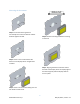
Mounting the thermostat Step 1: Locate the mounting buttons horizontally across the hole with the smaller diameter against the wall. Step 4: Remove mounting tab before mounting on the wall. Step 2: Screw in one screw and level the buttons so the display will be straight when installed. Step 5: Aligning the buttons with the holes in the back of the display. Press the display against the wall and gently slide the display down to lock it in place.
Initial setup instructions Setting the heat sources It is necessary to set up the heating sources prior to operating your thermostat. Press the settings button on the main screen. Select the heating sources button on the settings screen. Select furnace, Heat pump, or heat strip by pressing the icon. The red circle with a line through it will disappear indicating the heat source is available. Heat pump and heat strip cannot be selected together.
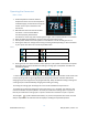
Operating the thermostat Main screen 1. Inside temperature shows the ambient temperature of the room. If the temperature is followed by (R), the thermostat is using the remote sensor input on the back of the thermostat. 2. WIFI indicator shows the state of the WIFI connection. Green indicates WIFI is connected properly, Red indicates connection to router only, bars indicate signal strength, and no symbol indicates no connection. 3. Raise and lower the temperature set point using the red and blue arrows. 4.
Away screen (Heat and cool set points) Away operation allows setting upper and lower limits for temperature with a non-operating area or “dead band” in the middle. This can be useful when setting a higher daytime cooling temperature and lower night time heating temperature. It can also be used to control the temperature extremes when you are away from the RV. The mode selected must be an automatic mode to allow both heating and cooling operation. 1.
Schedule screen Set points may be changed on a time-based schedule. The mode used will be the heating or cooling mode set on the main screen. Setting a change event 1. Events will show --:-- when the event is disabled. Press the hours position to set the hours. A flashing bar will appear under the hours along with up and down adjustment selectors. Use the adjustment selectors to change the hours. Press the minutes to move the flashing bar under the minutes and allow ¼ hour adjustments.
Settings Screen 1. Day mode (half sun icon shown above) will dim the display down to the screen saver set point after 30 seconds. Night mode (moon icon) will turn off the back light after 30 seconds. The display will brighten again once the touch screen is pressed. See (8) to set brightness. 2. The DIP switches icon is used to configure set behaviors of the thermostat. It must be used when installing the thermostat to set the available heat sources. See setting your heat sources for more details.
Gas Heat Override This feature turns on the gas furnace from an electric heat mode when the setpoint is five or mode degrees away from the ambient temperature and heating is required. It is only available on systems that have both gas and electric heating and is only active in electric heat or cool/electric heat modes. The feature can be disabled from the settings/ heat sources screen entered by using the dip switch icon.
Installation Troubleshooting The most common problems during installation are not matching the wires correctly and not seating the wires in the connector properly. The first step should always be to recheck the instructions and make sure the wires are seated properly. The second most common problem is not knowing the thermostat operation. If the system is running a heating or cooling cycle, the set point will turn red for heating and blue for cooling.
Appendix: First connection steps 1. This thermostat uses BLE which is a special implementation of Bluetooth. It is not necessary to “Pair” the thermostat with the phone but an account must be created for operation. 2. Start the app on your smart device. The app will open and if you have not entered your account information, it will ask you to create an account. Enter your name, email and a password at the prompts. The system will send a confirmation email to your inbox.