EasyTouch 351 Operating Manual Revision 1.5 1 ©2022 Micro-Air Corp June 15, 2022, revision 1.
Contents Installing the thermostat .............................................................................................................................. 3 Removing the old thermostat ................................................................................................................... 3 Using the push button terminals .............................................................................................................. 3 Wiring the thermostat ...................................
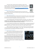
The EasyTouch 351 model thermostat was designed to replace certain Dometic™ single-zone thermostats. Original thermostats replaced by this model are a square design with a center LCD display and three buttons. If your thermostat is not of this style, please contact Micro-Air https://www.micro-air.com/SupportRequest to verify the thermostat you received is correct for your application. Installing the thermostat There are three steps to installing the thermostat. First remove your old thermostat.
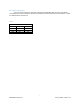
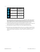
Wiring the thermostat There are three terminals on the back of EasyTouch labeled SIG, GND, and 12V. They will be connected to the push terminals on the back of the EasyTouch thermostat. Use the information in Table 1 to determine the connections. Table 1 Terminal Labels Style 1 GND COM +12V Style 2 -12V COMMS 12V+ EasyTouch GND SIG 12V 4 ©2022 Micro-Air Corp June 15, 2022, revision 1.
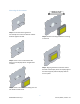
Mounting the thermostat Step 1: Locate the mounting buttons horizontally across the hole with the smaller diameter against the wall. Step 4: Remove mounting tab before mounting on the wall. Step 2: Screw in one screw and level the buttons so the display will be straight when installed. Step 5: Aligning the buttons with the holes in the back of the display. Press the display against the wall and gently slide the display down to lock it in place.
Initial setup instructions Available modes Control boards in this system send data to the display that determines the available modes. No configuration is necessary. Connecting remotely This thermostat may be operated remotely using either Bluetooth or WIFI. Apps may be loaded from the Google Play store or Apple App store. The first time the app is opened, it will ask to create an account. A WIFI connection on your smart device is necessary for this step.
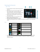
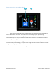
Operating the thermostat Main screen 1. Inside temperature shows the ambient temperature of the room. 2. WIFI indicator shows the state of the WIFI connection. Green indicates WIFI is connected properly, Red indicates connection to router only, bars indicate signal strength, and no symbol indicates no connection. 3. Raise and lower the temperature set point using the red and blue arrows. 4. Use the power button to turn the system on or off. Button is red for off and green for on. 5.
Table 3 Icon Indication Fan low Action Fan runs continually on low Fan high Fan runs continually on high Auto fan Fan cycles with compressor or electric element No Fan Fan off 7. Home-away-schedule icon. Pressing this button selects between these modes. Home mode is the normal operating mode using a single setpoint for temperature control. Schedule mode allows changing set points throughout the day programmatically.
Away screen (Heat and cool set points) Away operation allows setting upper and lower limits for temperature with a non-operating area or “dead band” in the middle. This can be useful when setting a higher daytime cooling temperature and lower night time heating temperature. It can also be used to control the temperature extremes when you are away from the RV. The mode selected must be an automatic mode to allow both heating and cooling operation. 1.
Schedule screen Set points may be changed on a time-based schedule. The mode used will be the heating or cooling mode set on the main screen. Setting a change event 1. Events will show --:-- when the event is disabled. Press the hours position to set the hours. A flashing bar will appear under the hours along with up and down adjustment selectors. Use the adjustment selectors to change the hours. Press the minutes to move the flashing bar under the minutes and allow ¼ hour adjustments.
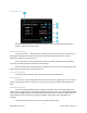
Settings Screen 1. Day/Night mode. Day mode (shown above) will dim the display down to the screen saver set point after 30 seconds. Night mode (moon icon) will turn off the back light after 30 seconds. The display will brighten again once the touch screen is pressed. See (7) to set brightness. 2. The DIP switches icon is used to view the modes set on the control board dip switches. 3. WIFI is used to view your WIFI settings and MAC address.
Gas Heat Override This function is handled by the control board and not the thermostat. It will activate when the outside temperature falls below the minimum heat pump operating temperature if available on the system. Smart device application only features Reset device This Bluetooth only feature allows resetting the display just as if you removed and restored power. Calibrate Touchscreen It is normally not necessary to recalibrate the touchscreen.
Installation Troubleshooting The most common problem is not knowing the thermostat operation. If the system is running a heating or cooling cycle, the set point will turn red for heating and blue for cooling. When the thermostat turns white, the heat pump, heat strip and furnace should all be off. The fan may continue to run for a while after the cycle completes. If a fan is left in a manual mode, it will not shut off.
Appendix A: Connecting remotely First connection steps 1. This thermostat uses BLE which is a special implementation of Bluetooth. It is not necessary to “Pair” the thermostat with the phone but an account must be created for operation. 2. Start the app on your smart device. The app will open and if you have not entered your account information, it will ask you to create an account. Enter your name, email and a password at the prompts. The system will send a confirmation email to your inbox.