
Product Manual

Work Pro Gasoline Air Compressor Manual 9
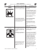
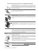
SAFETY RELIEF VALVE: This valve is designed to prevent system failures by reliev-
ing pressure from the system when the compressed air reaches a predetermined level.
The valve is preset by the manufacturer and must not be modied in any way. To verify
the valve is working properly, pull on the ring. Air pressure should escape. When the
ring is released, it will reseat.
PILOT VALVE: When the toggle is in the upright position, all air from the air compressor
is vented through the discharge mufer. This gives an easy start feature. For normal
operation, the toggle is in the 90° position.
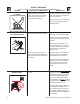
AIR INTAKE FILTER: This lter is designed to clean air coming into the pump. To
ensure the pump continually receives a clean, cool, dry air supply this lter must always
be clean and ventilation opening free from obstructions. Replace lter element when
necessary.
AIR TANK PRESSURE GAUGE: The air tank pressure gauge indicates the reserve
air pressure in the air tank (s).
PRESSURE REGULATOR: The air pressure coming from the air tank is controlled by
the regulator knob. Turn the pressure regulation knob clockwise to increase discharge
pressure, and counterclockwise to decrease discharge pressure. (Actual delivered
pressure may vary from pump maximum pressure rating)
OUTLET PRESSURE GAUGE: The outlet pressure gauge indicates the air pressure
available at the outlet side of the regulator. This pressure is controlled by the regulator
and is always less or equal to the air tank pressure.
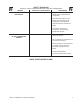
AIR TANK DRAIN VALVE: The drain valve is used to remove moisture from the air
tank(s) after the air compressor is shut off. NEVER attempt to open the drain valve
when more than 10 PSI of air pressure is in the air tank! To open the drain valve,
turn the knob counterclockwise.
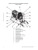
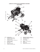
EXPLODED VIEW & EXPLANATION OF AIR COMPRESSOR FEATURES
OIL FILL PORT/VENT: Pour oil into the Oil Fill Port/Vent when required.
OIL SIGHT GLASS: The Oil Sight Glass displays the oil level in the pump. The oil
level should be at the center of the Oil Sight Glass. If low, add SAE 30W non-deter-
gent oil.
AIR COMPRESSOR PUMP: To compress air, the pistons move up and down in the
cylinders. On the downstroke, air is drawn in through the air intake valves while the
exhaust valves remain closed. On the upstroke, air is compressed, the intake valves
close and compressed air is forced out through the exhaust valves, into the discharge
line, through the pilot valve and into the air tank.
TOGGLE
DISCHARGE
MUFFLER
OPERATING
POSITION
EASY START
POSITION
TANK
PRESSURE
GAUGE
PRESSURE
REGULATOR
OUTLET
PRESSURE
GAUGE
DECREASE PRESSURE
COUNTER CLOCKWISE
INCREASE
PRESSURE
CLOCKWISE