
Operating instructions

75D0004 33
MLDV Series Gas Fireplace
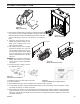
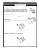
10.Turn blowers with discharge vent facing up. Slide the discharge
vent so that it is facing up. Slip discharge vent ange under the
ange bracket ush against the sidewall. Slide blower side tabs
over into side ange. Figure 52. The blower is now locked in
place.
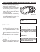
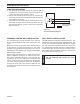
11. Attach the speed control to the un-
derside of the rebox using the sup-
plied velcro, locating as far to the
right or left as possible.
1. The thermal sensor clip is located
beneath the rebox oor near the
center. Slide the thermal sensor into
the clip until it snaps in place. Make
sure the terminals on the thermal
sensor are perpendicular to the clip.
Figure 53
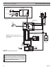
It is important to arrange the
blower wire harness so the wires
can not come in contact with blower
fan blades.
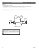
13. Connect wiring according to the wir-
ing diagram Figure 55.
14. Replace engine in reverse order of removal.
15. Plug in the blower.
16. Re-install rebrick, grate, logs, and glass door in reverse order of removal.
17. To test blower operation, set the variable speed blower on the LOW setting. Turn the replace on high.
The blower should turn on within 10 minutes.
18. If the blower does not turn on, turn the replace off and allow cooling. Unplug the blower. Using a jeweler’s
style screwdriver, turn the white dial on the side of the variable speed control 1/8 turn counterclockwise.
Figure 54. This will allow the blower motor to start at the low speed setting as the replace cycles on and
off. Retest the blower.
FP1981
blower install
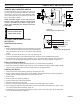
Figure 51 -
Blower Installation
Figure 53 -
Thermal Sensor Installation
Figure 54 -
Location of White Dial on Speed Control
KT503
blower magnets
11/08
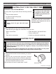
Magnet
KT503
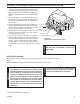
Figure 50 -
Magnet Installation
KT505
install blower
Start Position
Installed
Position
KT505
Figure 52 -
Blower Installation Position