
Operating instructions

3
75D0004
MLDV Series Gas Fireplace
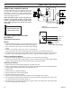
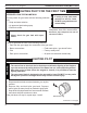
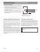
A remote wall switch and up to fteen (15) feet of 18
Ga. wire may be used with this appliance. Attach the
wall switch in a junction box at the desired location
on the wall. Figure 48. Do not extend beyond the wall
switch wire length provided.
NOTE:
Figure 48 -
Wiring Diagram for Wall Switch
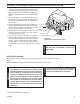
1. Before installing the blower, wire the receptacle into an elec-
trical circuit. This should be done before framing the replace.
Wire with minimum 60° C wire in accordance with prevailing
codes.
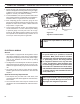
. Remove the external junction box cover by removing the
screw from the left side of the outside rebox wall. Junction box was installed at the factory.
3. The junction box cover has a factory installed “romex” style strain relief connector. After connecting
the wires, route the wire leads through this connector. Refer to the wiring diagram in Figure 49.
1. Always turn off the gas supply and allow the unit to cool down before proceeding.
. Clean the inside of the rebox (wall and oor), where the blower and wires will be installed. Make
sure the rebox wall and oor are clean and dry before mounting the blower.
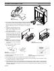
1. Remove the lower access panel by pulling up and away from unit.
. Remove glass frame by releasing the two () latches (500 Model has three (3) latches) below the
rebox opening and lifting glass frame up and away from unit.
3. Remove logs.
4. Remove grate from engine by lifting up.
5. Remove hearth brick and wall brick panels.
6. Disconnect the gas line to the valve.
7. Remove screws securing engine base to rebox oor and lift engine up to remove.
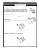
8. Two () magnetic strips have been supplied to secure each blower to the rebox oor. Place on bot-
tom of each blower before installing. Figure 50
9. The blowers are to be inserted at through the engine cutout in the rebox oor. Slide each blower
over to the sidewall location. Figure 51
FP1912
Junction box wiring
8/08
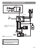
Figure 49 -
Junction Box Wiring Diagram
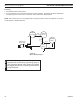
10V AC
60Hz
Factory Supplied
Not Supplied
ON
OFF
OPTIONAL REMOTE
WALL SWITCH
ON
OFF
OPTIONAL REMOTE
WALL SWITCH
PILOT
HI
LO
ON
OFF
TH
TP
TH/TP
ON
OFF
RS
FP1980
Dv wiring diagram