
Operating instructions

18
73D4125
KSTDV Series Gas Fireplace
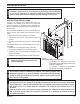
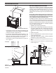
If the f oun-
d a t i o n i s
r e c e s s e d ,
u s e re c e s s
brackets (not
s u p p l i e d )
for securing
lower portion
of the snorkel.
Fasten brack-
ets to wall first,
then secure
t o s n o r k e l
with self drill-
ing #8 x 1/2
sheet metal
screws. It will
be necessary
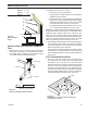
to extend vent pipes out as far as the protruding wall face.
Figure 19
FP1966
snorkel
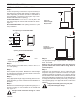
Figure 19 -
Snorkel Installation, Recessed Foundation
Foundation
Recess
Watertight Seal
Around Pipe
Sheet Metal
Screws
Wall Screws
Snorkel
FP1966
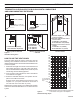
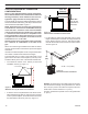
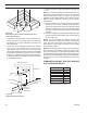
Install restrictor disc as shown in Figure 20 for vertically
vented applications.
Up to two (2) restrictor discs may be needed for 40' instal-
lation.
The two (2) restrictor discs suppled will work for most instal-
lations. If a third disc is needed order Part No. 56D3027.
This gas fireplace has been approved for,
• Vertical installations up to 40' (12 m) in height. Up to
a 10' (3 m) horizontal vent run can be installed within
the vent system using a maximum of two 90° elbows.
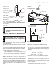
Figure 21
Horizontal sections of this vent system require a
minimum of 3" clearances to combustibles at the top of
the flue and 1" clearance at the sides and bottom until the
flue penetrates the outside wall. A minimum 1" clearance
all around the flue is acceptable at this point of penetration.
Unless the vertical run is 7Z\x feet or higher form floor of
fireplace, the clearance for the horizontal run is 1" on all
sides.
Max.
Height 40' (12.2m)
Min.
Height 8' (2.4 m)
Max. 10' (3m)
40' (12 m) Maximum Height
12' (3.7 m) Minimum Height
10' (3 m)
Maximum
Support Straps
Every 3'
24" (610 mm)
Min.
FP1387
Figure 21 -
Support Straps for Horizontal Runs
FP2707
restrictor disc
Restrictor Disc
Fireplace Collar
FP2707
Figure 20 -
Install Restrictor Disc
into Fireplace Collar
Vertical sections of this vent system require a minimum of
1" clearance to combustibles on all sides of the pipe.
• Up to two 45° elbows may be used within the horizontal
run. For each 45° elbow used on the horizontal plane,
the maximum horizontal length must be reduced by 18"
(457 mm).
Example: Maximum horizontal length
No elbows = 10’ (3 m)
1x45° elbows = 8.5’ (2.6 m)
2x45° elbows = 7’ (2.1 m)
• A minimum of an 8' (2.5 m) vertical rise is required.
• Two sets of 45°elbows offsets may be used within the
vertical sections. From 0 to a maximum of 8' (2.5 m)
of vent pipe can be used between elbows. Figure 22
• The maximum angular variation allowed in the system
is 270°. Figure 22
• The minimum height of the vent above the highest point
of penetration through the roof is 2' (610 mm).