
Operating instructions

73D4125
17
KSTDV Series Gas Fireplace
A
B
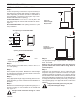
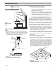
10’
90°
FP2546
Horizontal run
reduction
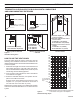
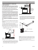
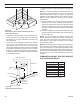
Example: Elbow 1 = 90°
Elbow 2 = 45°
Elbow 3 = 45°
Elbow 4 = 90°
Total Angular Variation = 270°
Figure 17 -
Maximum Elbow Usage
1
2
3
4
1
2
3
4
FP1383
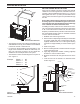
Max bends
24" (610 mm)
Minimum
FP1383
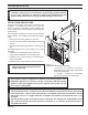
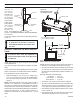
When it is not possible to meet the required vent terminal
clearances of 12" above grade level, a snorkel kit is recom-
mended. It allows installation depth down to 7" (178 mm)
below grade level. The 7" (178 mm) is measured from the
center of the horizontal vent pipe as it penetrates through
the wall.
If installing a snorkel, a minimum 24" vertical rise is neces-
sary. The maximum horizontal run with the 24” vertical pipe
is 36". This measurement is taken from the collar of the
fireplace (or transition elbow) to the face of the exterior wall.
See the Sidewall Venting Graph for extended horizontal
run if the vertical exceeds 24".
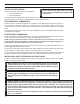
1. Establish vent hole through the wall.
2. Remove soil to a depth of approximately 16" below base
of snorkel. Install drain pipe. Install window well (not
supplied). Refill hole with 12" of coarse gravel leaving
a clearance of approximately 4" below snorkel. Figure
18
3. Install vent system.
4. Ensure a watertight seal is made around the vent pipe
coming through the wall.
5. Apply high temperature sealant caulking (supplied)
around the 5" and 8" snorkel collars.
6. Slide the snorkel into the vent pipes and secure to the
wall.
7. Level the soil so as to maintain a 4" clearance below
snorkel. Figure 18
Figure 16 -
Horizontal Run Reduction
FP2546
FP2134
below grade install
FP2134
Figure 18 -
Below Grade Installation
Screws
Minimum
4" Clearance
Ground
Window
Well
Gravel
Drain
Foundation
Wall
Firestop
24"
(610 mm)
Minimum
• The maximum number of 45° elbows permitted per side
wall installation is two (2). These elbows can be installed
in either the vertical or horizontal run.
• For each 45° elbow installed in the horizontal run, the
length of the horizontal run MUST be reduced by 18"
(457 mm). This does not apply if the 45° elbows are
installed on the vertical part of the vent system.
• The maximum number of elbow degrees in a system is
270°. Figure 17