KSTDV Series Direct Vent Gas Fireplace Model: KSTDV500 Installation and Operating Instructions WARNING If the information in these instructions is not followed exactly, a fire or explosion may result causing property damage, personal injury or loss of life. – Do not store or use gasoline or other flammable vapors and liquids in the vicinity of this or any other appliance. – WHAT TO DO IF YOU SMELL GAS • Do not try to light any appliance.
CONTENTS KSTDV Series Gas Fireplace Thank you and congratulations on your purchase of an MHSC Fireplace. PLEASE READ THE INSTALLATION AND OPERATION INSTRUCTIONS BEFORE USING THE APPLIANCE! IMPORTANT: Read all instructions and warnings carefully before starting installation. Failure to follow these instructions may result in a possible fire hazard and will void the warranty. Important Safety Information....................................... 3 Optional Fan/Blower Systems . ................................
IMPORTANT SAFETY INFORMATION KSTDV Series Gas Fireplace OWNER Please leave these instructions with the appliance. Please retain these instructions for future reference. WARNING INSTALLER • Read this owner’s manual carefully and completely before trying to assemble, operate, • • or service this fireplace. Any change to this fireplace or its controls can be dangerous.
IMPORTANT SAFETY INFORMATION & CODE APPROVAL 15. This appliance, when installed, must be electrically grounded in accordance with local codes or in the absence of local codes, with the National Electrical Code, ANSI/NFPA 70, or the Canadian Electrical Code, CSA C22.1. 16. Do not obstruct the flow of combustion and ventilation air in any way. Provide adequate clearances around air openings into the combustion chamber along with adequate accessibility clearance for servicing and proper operation. 17.
product features KSTDV Series Gas Fireplace product SPECIFICATIONS • This appliance has been certified for use with either natural or propane gas. See appropriate data plates. • This appliance is not for use with solid fuels. • The appliance is approved for bedroom or bedsitting • • • • room installations. The appliance must be installed in accordance with local codes if any. If none exist use the current installation code. ANSI Z223.1/NFPA 54 in the USA, CSA B149 in Canada.
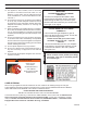
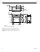
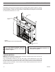
FIREPLACE & FRAMING DIMENSIONS KSTDV Series Gas Fireplace 25” (635 mm) Rough Opening Depth 1156O” (292 mm) 23” (584 mm) 1/2” or 5/8” Recessed Nailing Flange 50” (1270 mm) Rough Opening Width Rough Opening Height 456M” (108 mm) 44 6M” (1137 mm) 4456O” (1130 mm) 36” (914 mm) 39 6 ” (1007 mm) 30" 38 6 ” (762 mm) (981 mm) 24” (610 mm) 4956O” (1257 mm) Figure 2 Fireplace and Framing Dimensions 734126 NOTE: For exterior wall applications, outdoor facing kit DIMS DVKST KSTDV KST500SSDK is required.
pRE-INSTALLATION INFORMATION Before You Start Read this homeowner manual thoroughly and follow all instructions carefully. Inspect all contents for shipping damage and immediately inform your dealer if any damage is found. Do not install any unit with damaged, incomplete, or substitute parts. Check your packing list to verify that all listed parts have been received.
pRE-INSTALLATION INFORMATION KSTDV Series Gas Fireplace Fireplace Location Plan for the installation of your appliance. This includes determining where the unit is to be installed, the vent configuration to be used, framing and finishing details, and whether any optional accessories (i.e. blower, wall switch, or remote control) are desired. Consult your local building code agency to ensure compliance with local codes, including permits and inspections.
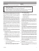
KSTDV Series Gas Fireplace CLEARANCES WARNING Clearances to combustibles Follow these instructions carefully to ensure safe installation. Failure to follow instructions exactly can create a fire hazard. The appliance cannot be installed on a carpet, tile or other combustible material other than wood flooring. If installed on carpet or vinyl flooring, the appliance shall be installed on a metal, wood or noncombustible material panel extending full width and depth of the appliance.
SECURE FIREPLACE TO FLOOR OR FRAMING KSTDV Series Gas Fireplace The fireplace must be secured to the floor and/or to framing studs as shown in Figure 6 . Use four (4) wood screws or masonry/ concrete screws to secure fireplace to the floor. Use four (4) screws to attach fireplace to framing. The side brackets or nailing flanges are designed to accommodate two wall boards thicknesses, 1/2" or 5/8".
KSTDV Series Gas Fireplace WARNING VENTING INSTALLATION Read all instructions completely and thoroughly before attempting installation. Failure to do so could result in serious injury, property damage or loss of life. Operation of improperly installed and maintained venting system could result in serious injury, property damage or loss of life. installation precautions Consult local building codes before beginning the installation.
Venting installation installation planning There are two basic types of direct-vent installation: • Horizontal Termination • Vertical Termination WARNING KSTDV Series Gas Fireplace Never run the vent pipe down. This may cause excessive temperatures which could cause a fire. It is important to select the proper length of vent pipe for the type of termination you choose. It is also important to note the wall thickness. for horizontal termination Select the amount of vertical rise desired.
KSTDV Series Gas Fireplace venting installation General Venting Information - Termination Location INSIDE CORNER DETAIL G V H A D L V E C B V F B Fixed Closed Ope V B Figure 7 Termination Locations B V Operable rable B B J A CFM145a V VENT TERMINATION V V Fixed Closed X AIR SUPPLY INLET X M I V K X AREA WHERE TERMINAL IS NOT PERMITTED Canadian Installations1 US Installations2 A = Clearance above grade, veranda, porch, 12” (30 cm)CFM145a 12” (30 cm) DV Termin Location 5/01/0
venting installation KSTDV Series Gas Fireplace termination clearances for buildings with combustible and noncombustible exteriors D C C G G=6" (152mm) V V V Inside Corner E F=6" (152mm) F Combustible – 6" (152 mm) Noncombustible – 2" (51mm) Outside Corner C = Maximum depth of 48" (1219mm) for alcove location D = Minimum width for back wall of alcove location Combustible - 38" (965mm) Noncombustible - 24" (610mm) E = Clearance from corner in alcove location Combustible - 6" (152mm) Noncombust
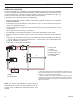
venting installation KSTDV Series Gas Fireplace Vertical Sidewall Installation Step 1 Locate vent opening on the wall. It may be necessary to first position the fireplace and measure to obtain hole location. Depending on whether the wall is combustible or noncombustible, cut opening to size. Figure 10 (For combustible walls first frame in opening.) Combustible Walls: Cut a 10Z\x”H x 10Z\x”W (267 x 267 mm) hole through the exterior wall and frame as shown.
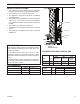
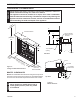
KSTDV Series Gas Fireplace venting installation VERTICAL/Horizontal termination configurations Max. 36" (914mm) Max. 20" system mainSince it is very important that the venting tain its balance between the combustion (508mm) air intake and the flue gas exhaust, certain limitations as to vent configurations apply and must be strictly adhered to. 24" (610 mm) Min. *NOTE: With a 24" rise, the horizontal run must be 36".
KSTDV Series Gas Fireplace ventING installation Below Grade Installations 90° When it is not possible to meet the required vent terminal clearances of 12" above grade level, a snorkel kit is recommended. It allows installation depth down to 7" (178 mm) below grade level. The 7" (178 mm) is measured from the center of the horizontal vent pipe as it penetrates through the wall. B A Ensure that sidewall venting clearances are observed.
venting installation KSTDV Series Gas Fireplace Restrictor Disc If the foundation is recessed, Snorkel use recess brackets (not s u p p l i e d ) Foundation for securing Recess lower portion Wall Screws of the snorkel. Fasten brackets to wall first, Watertight Seal Sheet Metal then secure Around Pipe Screws to snorkel with self drilling #8 x 1/2 FP1966 sheet metal Figure 19 screws. It will Snorkel Installation, Recessed Foundation be necessary to extend vent pipes out as far as the protruding wall face.
KSTDV Series Gas Fireplace venting installation Example: Elbow 1 Elbow 2 Elbow 3 Elbow 4 Total Angular Variation = = = = = 90° 45° 45° 90° 270° For optimal flame appearance, a restrictor disk is necessary on straight vertical runs of 10' of more. • Runs may not incorporate elbows. • The disk is part number 56D3027 and is included in installation manual packet.
venting installation KSTDV Series Gas Fireplace 101 /" 10 1 2 /2" FP1970 Firestop Nails Figure 25 If Area Above is Not a Room, Install Firestop above Framed Hole as Shown 2. Assemble the desired lengths of pipe and elbows necessary to reach from FP1970 the burner system flue up through the firestop. Be sure pipe and elbow connections are firestop no room fully twist-locked. 3. Cut a hole in the roof using the locating hole as a center point.
fireplace installation KSTDV Series Gas Fireplace check gas type Use proper gas type for the fireplace you are installing. If you have conflicting gas type, do not install fireplace. See dealer where you purchased the fireplace for proper fireplace according to your gas type. A qualified installer or service person must connect appliance to gas supply. Follow all local codes.
fireplace installation KSTDV Series Gas Fireplace CAUTION WARNING INSTALL GAS SUPPLY LINE Only persons licensed to work with gas piping may make the necessary gas connections to this appliance. A manual shutoff valve must be installed upstream of the appliance. Union tee and plugged 1/8" NPT pressure tapping point should be installed upstream of the appliance. Figure 28 NOTE : The gas line connection may be made using 1/2" rigid tubing or an approved flex connector.
CHECK GAS PRESSURE and ELECTRICAL INSTALLATION Pressure Inlet FP1909a Pressure Outlet Pilot Adjustment Screw Figure 29 Signature Command Valve WARNING 1. Check gas type. The gas supply must be the same as stated on the appliance’s rating decal. If the gas supply is different from the fireplace, STOP! Do not install the appliance. Contact your dealer immediately. 2. To ease installation, a 24" (610 mm) flex line with manual shut-off valve has been provided with on this appliance.
ELECTRICAL INSTALLATION KSTDV Series Gas Fireplace JUNCTION BOX WIRING 1. This should be done before framing the fireplace. Wire the receptacle into an electrical circuit. Wire with minimum 60° C wire in accordance with prevailing codes. 2. Remove the external junction box cover by removing the screw from the side of the outside firebox wall. Junction box was installed at the factory. 120V AC 3. The junction box cover has a factory installed “romex” style 60Hz strain relief connector.
ELECTRICAL INSTALLATION Light 300 Watt Max KSTDV Series Gas Fireplace A/C Module To Outlet Pilot Optional Blower 300 Watt Max Rear Burner Solenoid 300 Watt Max RF Receiver ON/OFF Button A/C Module Control Board Black / Thermopile Red / Thermopile Sensor Conversion NG/LP Ignitor / Sparker Plug-in Connector Control Board to Command Center NOTE: Wall switch wires must be connected together if a wall switch is not being used.
Optional fan blower system The black and white wires on the AC box wiring harness are marked ‘Blower’, ‘Light’ and ‘Aux’. It is important to use the wires marked ‘Blower’ or the control will not work correctly. WARNING WARNING Electrical Grounding Instructions: This appliance is equipped with a three-prong (grounding) plug for your protection against shock hazard and should be plugged directly into a properly grounded three-prong receptacle.
KSTDV Series Gas Fireplace glass removal Glass Frame Removal 1. Remove the plate located in front of the glass at the bottom. 2. Remove rod provided for screen assembly located beneath the cover plate. 3. Rotate the access doors on the right and left side of the glass toward the glass. 4. Remove glass frame by releasing the three latches located at the top of the firebox. Tilt glass away from the unit, lift glass frame up and away from the unit.
final installation KSTDV Series Gas Fireplace Wall Brick Light Box Cover Figure 36 Install Brick Floor Brick Hearth Brick FP2592 ROCK WOOL PLACEMENT Place rock wool evenly in dime-sized pieces over front and rear burner both in front and behind rear grate. For the middle burner, place the rock wool only on the carry-over areas FP2592 between the flames. To better enable the gas to permeate the rock wool, apply the rock install brick wool in light, fluffy pieces.
KSTDV Series Gas Fireplace log placement Log #1 LOG PLACEMENT 1. From the back side of the unit (with the controls on your left) and holding log #1 in your left hand with the widest end of the log away from you, place the log over the pilot, making sure to locate notches in log over the first tine from left on the near side and the first two tines from the left on the front side of the unit. Figure 38 LG726 Log #2 2.
log placement KSTDV Series Gas Fireplace 4. Holding log #4 in your left hand with the beveled end down, place the log on the key of log #1 closest to you. Make sure to locate the notch at the beveled end of the log over the third tine from the left. The inside edge of the log should rest against log #3. Figure 41 LG729 5. Move to the other side of the unit to place the remaining logs. Log #4 6.
KSTDV Series Gas Fireplace log placement 7. Hold log #6 in your left hand with the narrow cut end of the “Y” toward you and pointing up. Place the log on the key on the top of log #2 with the bottom of the log resting securely on top of the second tine from the left creating a “V” shape with log #5. Figure 43 LG731 Log #6 8. Hold log #7 with the “Y” pointing away from you and place the log on the notch located on the top of log #3 angling the narrow end of the log slightly down and behind log #5. 9.
OPERATING INSTRUCTIONS KSTDV Series Gas Fireplace WARNING for your safety read before lighting If you do not follow these instructions exactly, a fire or explosion may result causing property damage, personal injury or loss of lie. A. This appliance is equipped with an ignition device which automatically lights the pilot. Refer to the instructions. B. BEFORE OPERATING smell all around the appliance area for gas.
KSTDV Series Gas Fireplace OPERATING INSTRUCTIONS OPERATing INSTRUCTIONS 1. STOP! Read the safety information above. 2. This appliance is equipped with an ignition device which automatically lights the burner. Do not try to light the burner by hand. 3. With five (5) minutes to clear out any gas. Then smell for gas, including near the floor. If you smell gas, STOP! Follow "B" in the safety information on page 32. If you do not smell gas, go to next step. 4. Press the master switch to the "ON" (-) position.
KSTDV Series Gas Fireplace SIGNATURE COMMAND SYSTEM OPERATION INSTRUCTIONS FEATURES RF Receiver ON/OFF Command Center To Thermopile To Sensor • Easy Access Function Operation and System Configuration • Operation Confirmation/Fault Diagnostic Indications (LED/Buzzer) • ON/OFF/HI/Med/Low Operation • Optional Wall Mounting Control Board NG/LP Conversion To Command Center • Electronic Ignition • Pilot Lockout safety feature • Electric Power Regeneration from Thermopile to save • • • • • • • To Sparker
SIGNATURE COMMAND SYSTEM OPERATION INSTRUCTIONS KSTDV Series Gas Fireplace SYSTEM CONFIGURATION/SETUP All System configuration/setup is done on the Command Center. NOTE: When using On/Off wall switch, the switch must be in the ON position to perform all configuration set ups at the command center. Intermittent/Standing Pilot Setup (Default intermittent) 1. Holding the ON button on the Command Center while turning on the master switch will toggle between standing pilot and intermittent pilot. 2.
KSTDV Series Gas Fireplace SIGNATURE COMMAND SYSTEM OPERATION INSTRUCTIONS FUNCTIONS/OPERATION (with Command Center) Turning on the fireplace 1. Turn on the master switch and wait for a beep. 2. Press the ON button on the Command Center or turn on wall switch. Pilot will light and burner will come on High setting or last memory setting (See Turning Off Fireplace below). For memory feature. Pilot Safety Lockout Function 1.
WARNING Figure 26 shows the display of the TSFRSC LCD. Information Bar The information bar shows the room temperature, the “sending signal” radio icon, the low battery indication icon, the child-proof icon, and the flame icon. This area doesn’t have touch buttons. • The room temperature will always be shown after • • • Adjustment Controls Logo Bar n Function Areas of the LCD Display • Menus Turn appliance OFF (at the Master Switch) if you are away from your house for an extended period of time.
KSTDV Series Gas Fireplace TOUCH SCREEN REMOTE CONTROL OPERATION Setting Privacy Code on Transmitter: Figure 48 Battery Door The remote transmitter privacy code is preset in factory. In the event of activation or interference from other nearby transmissions, change the code using the following procedures (learn function must be performed after changing the code): FP2650 WARNING 1.
TOUCH SCREEN REMOTE CONTROL OPERATION 1. Press the ON/up button to turn on the fireplace. The flame icon on the LCD displays High. 2. Press the OFF/down button to decrease the flame height and turn off the fireplace. When the OFF/down button is pressed for three times, the flame icon changes form High to Medium, to Low, then to Off. 3. If the OFF button is held for more than 3 seconds at any flame height, the fireplace will be turned off and the flame icon disappears. Figure 51 4.
KSTDV Series Gas Fireplace TOUCH SCREEN REMOTE CONTROL OPERATION is no manual flame height adjustment. The fan speed will also automatically adjust if turned on. NOTE: When entering the Smart Mode function there will be a 1 second delay for the flame and blower adjustment. When Smart Mode operates automatically, there can be up to a 3 minute delay for flame/blower adjustment. Smart Mode checks temperatures every 3 minutes. Also see AUX Control. 1. When Set Temp. is 3° F or higher than Room Temp.
TOUCH SCREEN REMOTE CONTROL OPERATION 4. After the signal is sent, the On/up and Off/down buttons become flame height controller again. 5. When the light button is flashing, slide up and down on the arrow buttons will turn the light brightness to HIGH or Off directly without pressing the light button again to confirm AUX Control (Rear Burner On/Off Control) The AUX control function is used to turn on or turn off the rear burner connected to the AC module of the Signature Command System.
KSTDV Series Gas Fireplace TOUCH SCREEN REMOTE CONTROL OPERATION n Using the Mounting Base The transmitter comes with a mounting base which allows you to hang the transmitter on the wall. 1. Secure the mounting base on the wall with supplied screws. For best viewing angle, make it the same height as your eyes. 2. Hang the transmitter on the hook of the mounting base, then push down so the transmitter is flush to the mounting base. Figure 59 FP2674 TROUBLESHOOTING mounting base Symptom Causes Action 1.
WARNING cleaning and maintenance KSTDV Series Gas Fireplace Turn off gas before servicing fireplace. It is recommended that a qualified service technician perform these check-ups at the beginning of each heating season Sensor Thermopile Burner, Pilot and Control Compartment Keep the control compartment, logs, and burner areas surrounding the logs clean by vacuuming or brushing at least twice a year.
KSTDV Series Gas Fireplace cleaning and maintenance Vent SysteM The fireplace and venting system should be inspected before initial use and at least annually by a qualified field service person. Inspect the external vent cap on a regular basis to make sure that no debris is interfering with the airflow. Inspect entire venting system to ensure proper function. Glass Door Thoroughly clean the inside of the glass door after using the fireplace for ten hours. Periodically clean the glass door as necessary.
KSTDV Series Gas Fireplace troubleshooting SIGNATURE COMMAND SYSTEM OPERATION Install batteries and/or plug in the AC board FAULT No beep in about 8 seconds A Using battery? Make sure Command Center and the control board are connected by a 2 feet or 15 feet cable After the beep Flip the master switch (rocker switch) to the ON position Press the ON button on the Command Center No beep or no sound from the valve indicating pilot solenoid open B No sparking on the pilot C Sparking doesn’t contin
REPLACEMENT PARTS KSTDV Series Gas Fireplace 2 6 3 1 7 5 9 8 firebox components and accessories Item 1. 2. 3. 4. 5. 6. 7. 8. 9. Description Qty.
REPLACEMENT PARTS KSTDV Series Gas Fireplace SIGNATURE COMMAND SYSTEM 25 2 17 12 24 17 13 11 18 27 26 27 13 23 26 15 16 28 14 5 22 1 3 4 29, 30 730024 KHLDV SG parts 12/08 73D4125 47
REPLACEMENT PARTS KSTDV Series Gas Fireplace SIGNATURE COMMAND SYSTEM Item Description Qty. 1. 2. 3. 4. 5. 6. 7. 8. 9. 10. 11. 12. 13. 14. 15. 16. 17. 18. 19. 20. 21. 22. 23. 24. 25. 26. 27. 28. 29. 30. 31. 32. 33. 34. Gas Valve Assembly 1 Pilot Assembly 1 Control Box 1 AC Module 1 Command Center 1 Tube, Tee to Front Burner 1 Tube between Tees 1 Tube, Solenoid to Mid.
REPLACEMENT PARTS KSTDV Series Gas Fireplace logs Item 1. 2. 3. 4. 5. 6. 7. 8. Description Qty.
REPLACEMENT PARTS KSTDV Series Gas Fireplace ACCESSORIES 1 6 2 7 8 3 9 5 4 10 Herringbone Standard Cottage Cottage Tavern Ref. Description Qty. Clay Red Brown 1. Brick, Wall Eng. Side 1 73D4127 73D4132 73D4149 2. Brick, Wall Air Side 1 73D4128 73D4133 73D4150 734126 3. Brick, Floor 2 73D4129 73D4134 73D4151 DVKST brick parts 4. Brick, Front, Left 2 73D4130 73D4135 73D4152 5. Brick, Front, Right 2 73D4131 73D4136 73D4153 Herringbone Pattern 6. Brick, Wall Eng. Side 1 ---7.
REPLACEMENT PARTS KSTDV Series Gas Fireplace VENT components 1 2 3 4 HO T 10 5 6 9 7 8 730024 KHLDV vent parts 73D4125 51
KSTDV Series Gas Fireplace REPLACEMENT PARTS Vent Components for 5" x 8" Current Old Simpson Simpson Duravent Duravent Qty./ or MHSC or MHSC Selkirk Item Box Description Part no. Part no. Part no.
KSTDV Series Gas Fireplace 73D4125 53
KSTDV Series Gasfor Fireplace Requirements the Commonwealth of Massachusetts This product must be installed by a licensed plumber or gas fitter when installed within the Commonwealth of Massachusetts. of eight (8) feet above grade directly in line with the exhaust vent terminal for the horizontally vented gas fueled heating appliance or equipment. The sign shall read, in print size no less than one-half (1/2) inch in size, “GAS VENT DIRECTLY BELOW, KEEP CLEAR OF ALL OBSTRUCTIONS”.
KSTDV Series Gas Fireplace Limited lifetime warranty policy Lifetime Warranty The following components are warranted for life to the original owner, subject to proof of purchase: Firebox, Combustion Chamber, Heat Exchanger, Grate and Stainless Steel Burners. Five Year Warranty The following components are warranted five (5) years to the original owner, subject of proof of purchase: Ceramic Fiber Logs.
KSTDV Series Gas Fireplace Efficiency Ratings Model EnerGuide Ratings Fireplace Efficiency (%) KSTDV500NTSC 77.30 KSTDV500PTSC 74.30 D.O.E. (AFUE%) 67.40 66.35 MHSC 149 Cleveland Drive • Paris, Kentucky 40361 www.mhsc.