
Operating instructions

20306750
29
Designer Series Direct Vent Gas Fireplace
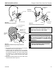
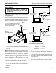
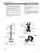
D. Attaching exible venting to vertical termination
assemblies.
1. When using Duravent pipe, an Vermont Cast-
ings Group ex-to-pipe adapter and/or rigid pipe
section(s) is required to connect the exible vent
assembly to the vertical termination by using
three self-penetrating screws.
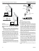
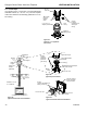
2. Review Figure 44 and corresponding instruc-
tions for proper overlap, clamp and screw place-
ment.
3. Three each self-penetrating screws are drilled
opposite one another and below the gear
clamp.
4. Use only listed and approved terminations and
accessories, installed per the installation instruc-
tions and Figure 43.
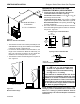
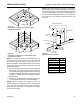
E. Installing exible venting to horizontal termination
assemblies.
1. Connect the 5" exible vent to the horizontal
termination as in Figure 45.
2. Connect the 8" exible vent to the termination
ring as in Figure 45.
3. Review Figure 45 for proper overlap and clamp
placement.
4. Three each self-penetrating screws are drilled
opposite one another and below the gear lamp.
5. Use only listed an approved terminations and
accessories, installed per the termination instruc-
tions and Figure 45.
FP1974
typical flex install
Termination
Cap
Storm Collar
Roof Support
Flashing
Rigid Pipe
Length
Flex to Pipe
Adapter
Firestop
UL1777 Flex
PIpe
Figure 43 -
Typical Vertical Flex Vent Installation
FP1975
pipe connection
Screws
(3 Places
equidistant
just above
gear clamp)
Rigid Pipe Length
Flex to Pipe Adapter
Gear Clamp
1
3
⁄4" Flexible Pipe and Adapter
Outer Collar Overlap
UL1777 Flex Vent
Figure 44 -
Typical Pipe Connection
Gear
Clamp
FP1976
horizontal flex
Screws
(3 Places equidistant just
above gear clamp)
Gear Clamp
UL1777 Flex Vent
1
3
⁄4" Flexible Pipe and
Collar Overlap
Vermont Castings
Group Horizontal
Vent Termination
Figure 45 -
Typical Horizontal Flex Vent Installation
DVFF8A/8 5" x 8" to
5" x 8" Flex Adapter
FP1974
VENTING INSTALLATION