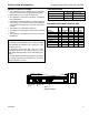
Designer Series Direct Vent Gas Fireplace Installation and Operating Instructions Models: STLDV(N/P)SCSB, PFLDV(N/P)SCSB, CRLDV(N/P)SCSB, CLLDV(N/P)SCSB CERTIFIED WARNING: FIRE OR EXPLOSION HAZARD Failure to follow safety warnings exactly could result in serious injury, death or property damage. • • • Do not store or use gasoline or other flammable vapors and liquids in the vicinity of this or any other appliance. WHAT TO DO IF YOU SMELL GAS – Do not try to light any appliance.
CONTENTS Designer Series Direct Vent Gas Fireplace Thank you and congratulations on your purchase of an Vermont Castings Group Fireplace. PLEASE READ THE INSTALLATION AND OPERATION INSTRUCTIONS BEFORE USING THE APPLIANCE! IMPORTANT: Read all instructions and warnings carefully before starting installation. Failure to follow these instructions may result in a possible fire hazard and will void the warranty. Important Safety Information......................................3 Code Approval..................
IMPORTANT SAFETY INFORMATION Designer Series Direct Vent Gas Fireplace OWNER Please leave these instructions with the appliance. Please retain these instructions for future reference. WARNING INSTALLER • Read this owner’s manual carefully and completely before trying to assemble, operate, or service this • • fireplace. Any change to this fireplace or its controls can be dangerous.
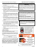
Designer Series Direct Vent Gas Fireplace IMPORTANT: PLEASE READ THE FOLLOWING CAREFULLY It is normal for fireplaces fabricated of steel to give off some expansion and/or contraction noises during the start up or cool down cycle. Similar noises are found with your furnace heat exchanger or car engine. IMPORTANT: PLEASE READ THE FOLLOWING CAREFULLY It is not unusual for gas fireplace to give off some odor the first time it is burned. This is due to the manufacturing process.
Designer Series Direct Vent Gas Fireplace INSTALLATION INFORMATION PRODUCT SPECIFICATIONS • This appliance has been certified for use with either • • • • • • natural or propane gas. See appropriate data plates. This appliance is not for use with solid fuels. The appliance is approved for bedroom or bedsitting room installations. The appliance must be installed in accordance with local codes if any. If none exist use the current installation code. ANSI Z223.1/NFPA 54 in the USA, CSA B149 in Canada.
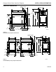
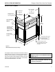
Designer Series Direct Vent Gas Fireplace FIREPLACE DIMENSIONS INSTALLATION INFORMATION Centerline of Flue Outlet 12" (305 mm) 11³⁄₄” (298 mm) 47⁷⁄₈” (1216 mm) 25³⁄₄” (654 mm) 34” (864 mm) 35⁹⁄₁₆” (903 mm) 41⁷⁄₈” (1064 mm) 28¹⁄₄” (718 mm) 37⁷⁄₈” (962 mm) 1¹⁄₄" (32 mm) 33¹⁄₁₆” (840 mm) 3³⁄₁₆” (81 mm) 23" (584 mm) 38⁹⁄₁₆” (979 mm) 7⁷⁄₈” (200 mm) 49⁹⁄₁₆” (1259 mm) FP2851 Figure 2 STLDV (See-thru) Fireplace Dimensions FP2851 LDV see thru dims Centerline of Flue Outlet 11³⁄₄” (298 mm) 7⁷⁄₈”
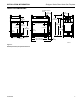
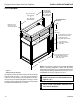
Designer Series Direct Vent Gas Fireplace INSTALLATION INFORMATION FIREPLACE DIMENSIONS Centerline of Flue Outlet 11³⁄₄” (298 mm) 7⁷⁄₈” (200 mm) 21” (533 mm) 28¹⁄₄” (718 mm) 25³⁄₄” (654 mm) 47⁷⁄₈” (1216 mm) 35⁹⁄₁₆” (903 mm) 41⁷⁄₈” (1064 mm) 28¹⁄₄” (718 mm) 34” (864 mm) 37⁷⁄₈” (962 mm) 1¹⁄₄" (32 mm) 1¹⁄₄" (32 mm) 18¹⁄₂” (470 mm) 12" (305 mm) 5¹⁄₈” 1¹⁄₈” (130 mm) (29 mm) 33¹⁄₁₆” (840 mm) 38⁹⁄₁₆” (979 mm) 46³⁄₈” (1178 mm) 23" (584 mm) 7⁷⁄₈” (200 mm) FP2853 Figure 4 PFLDV (Peninsula) Fireplace
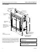
Designer Series Direct Vent Gas Fireplace INSTALLATION INFORMATION STLDV FRAMING 23" (1/2" Drywall) or Adjustable to 22³⁄₄” (5/8” Drywall) Remove box and Insulation for Top Vent Configurations Noncombustible Material CL 7 (17 ” 8m m Min ) . 4 (10 ” 2m m Min ) . 8¹¹ (22 ⁄₁₆” 1m m Min ) . Fold Outer Tabs and Nail to Framing Members 48³⁄₁₆” (1224 mm) NOTE: Glass centerline is off center from rought framing dimensions.
Designer Series Direct Vent Gas Fireplace INSTALLATION INFORMATION CRLDV/CLLDV FRAMING Remove box and Insulation for Top Vent Configurations 46¹⁄₈” (1172 mm) (1/2” Drywall) or 46” (1168 mm) (5/8” Drywall) 27¹⁄₂” (699 mm) (1/2” Drywall) or 27³⁄₈” (696 mm) (5/8” Drywall) Noncombustible Material 4¹ (114 ⁄₂” mm Min ) . , ⁄₁₆” 8¹¹ ) Min m m 221 ( 7” ) mm 8 (17 in.
Designer Series Direct Vent Gas Fireplace INSTALLATION INFORMATION STLDV FRAMING 23” (584 mm) (1/2” Drywall) or Adjustable to 22³⁄₄” (578 mm) (5/8” Drywall) 46¹⁄₈” (1172 mm) (1/2” Drywall) or 46” (1168 mm) (5/8” Drywall) Noncombustible Material Remove box and Insulation for Top Vent Configurations 48³⁄₁₆” (1224 mm) , ⁄₁₆” 8¹¹ ) Min m m 221 ( 7” ) m 8m (17 in.
Designer Series Direct Vent Gas Fireplace INSTALLATION INFORMATION BEFORE YOU START FIREBOX FRAMING Read this homeowner manual thoroughly and follow all instructions carefully. Inspect all contents for shipping damage and immediately inform your dealer if any damage is found. Do not install any unit with damaged, incomplete, or substitute parts. Check your packing list to verify that all listed parts have been received.
Designer Series Direct Vent Gas Fireplace INSTALLATION INFORMATION FIREPLACE LOCATION Plan for the installation of your appliance. This includes determining where the unit is to be installed, the vent configuration to be used, framing and finishing details, and whether any optional accessories (i.e. blower, wall switch, or remote control) are desired. Consult your local building code agency to ensure compliance with local codes, including permits and inspections.
Designer Series Direct Vent Gas Fireplace INSTALLATION INFORMATION WARNING CLEARANCES TO COMBUSTIBLES 12” Follow these instructions carefully to ensure safe installation. Failure to follow instructions exactly can create a fire hazard. Noncombustible Material to Top of Standoffs 6” 16” The appliance cannot be installed on a carpet, tile or other combustible material other than wood flooring.
WARNING Designer Series Direct Vent Gas Fireplace Read all instructions completely and thoroughly before attempting installation. Failure to do so could result in serious injury, property damage or loss of life. Operation of improperly installed and maintained venting system could result in serious injury, property damage or loss of life. INSTALLATION PRECAUTIONS Consult local building codes before beginning the installation. The installer must make sure to select the proper vent system for installation.
Designer Series Direct Vent Gas Fireplace Screws Flue Pipe Cover WARNING VENTING INSTALLATION After conversion to top vent configuration, the 5" (127 mm) flue pipe should be concentric with the 8" (203 mm) outer collar within 1/4". Flue Cover Screws Flue Pipe Adapter FP2833 Figure 12 Remove 16 screws from Flue Pipe Adapter and Flue Pipe Cover 4. Remove six (6) screws securing the flue pipe to the back of the intake box and remove the pipe and gasket. Figure 13 5.
This fireplace must be vented to the outside. The venting system must NEVER be attached to a chimney serving a separate solid fuel burning appliance. Each gas appliance must use a separate vent system. Do not use common vent systems.
Designer Series Direct Vent Gas Fireplace • Horizontal Termination • Vertical Termination It is important to select the proper length of vent pipe for the type of termination you choose. It is also important to note the wall thickness. FOR HORIZONTAL TERMINATION Select the amount of vertical rise desired. All horizontal run of venting must have 1/4" rise for every 12" of run towards the termination below 71⁄2' of vertical rise from floor of fireplace.
Designer Series Direct Vent Gas Fireplace VENTING INSTALLATION TERMINATION LOCATION INSIDE CORNER DETAIL V G H A D L V E C B V F B Fixed Closed B V Ope Operable rable V B V B J X B V VENT TERMINATION X AIR SUPPLY INLET M I A CFM145a Termination Locations V Fixed Closed V K X AREA WHERE TERMINAL IS NOT PERMITTED CANADIANCFM145a INSTALLATIONS1 DV Termin Location 5/01/01 Rev.
Designer Series Direct Vent Gas Fireplace VENTING INSTALLATION Termination Clearances Termination clearances for buildings with combustible and noncombustible exteriors. Alcove Applications* Inside Corner Outside Corner G= Combustible 6" (152 mm) G Noncombustible 2" (51 mm) V F= Combustible 6" (152 mm) Noncombustible 2" (51 mm) V C V O F Balcony with perpendicular side wall Balcony with no side wall D C E E = Min. 2” (51 mm) for non-vinyl sidewalls Min.
Designer Series Direct Vent Gas Fireplace REAR WALL VENT INSTALLATION (5" x 8" VENTING ONLY) When installed as a rear vent unit, this appliance may be vented directly to a termination located on the rear wall behind the appliance. Only an Vermont Castings Group brand termination is allowed for this application. • The maximum horizontal distance between the rear of the appliance and the termination is 20" (508 mm). Figure 19 Maximum 20" (508 mm) VENTING INSTALLATION 2.
Designer Series Direct Vent Gas Fireplace VENTING INSTALLATION Vent Cap Inerior Wall Surface Vent Cap (Horizontal Termination) Firestop T HO Apply Mastic to all Four Sides FP1957 Wood Screw Figure 22 Install Horizontal Termination Screw Figure 24 Install Firestop on Horizontal Vent Pipe 5DT-VS (Not required for Vermont Castings Group termination) Termination T HO FP1956 Nut Do not recess vent termination into any wall. This will cause a fire hazard.
WARNING Designer Series Direct Vent Gas Fireplace When installing the appliance as a rear vent unit, the 90° or 45° transition elbow attached directly to the rear of the unit is NOT INCLUDED in the following criteria and calculations and, unless specifically mentioned, should be ignored when calculating venting layouts.
Designer Series Direct Vent Gas Fireplace VENTING INSTALLATION B 7' A 10' Horizontal 90° Elbow = 3' Reduction 7'6" A + B = 17' Maximum HORIZONTAL WITH VERTICAL RISE (THROUGH-THE-WALL) APPLICATIONS 1. Locate and cut the vent opening in the wall. For combustible walls first frame in opening. Combustible Interior Walls: Cut a 121⁄2"H x 101⁄2" W hole through the interior wall. Combustible Exterior Walls: Cut a 101⁄2"H x 101⁄2"W square hole through the exterior wall frame.
Designer Series Direct Vent Gas Fireplace 1. Locate and cut the vent opening in the wall. For combustible walls first frame in opening. Combustible Interior Walls: Cut a 111⁄2"H x 91⁄2" W hole through the interior wall. Combustible Exterior Walls: Cut a 91⁄2"H x 91⁄2"W square hole through the exterior wall frame. Figure 31 Noncombustible Walls: Hole opening should be 71⁄2" (190 mm) in diameter. 2. The center of the hole should line up with the center line of the horizontal rigid vent pipe end.
Designer Series Direct Vent Gas Fireplace VENTING INSTALLATION NOTICE VERTICAL THROUGH-THE-ROOF APPLICATIONS A restrictor disc must be installed on vertical terminations that are higher than 12' (366 cm). 10' Maximum 40' Maximum Height 8' Minimum Height Install restrictor disc as shown in Figure 34 for vertically vented applications. Up to two (2) restrictor discs may be needed for 40' installation. Support Straps Every 3' The two (2) restrictor discs suppled will work for most installations.
Designer Series Direct Vent Gas Fireplace VENTING INSTALLATION Roof Flashing 1 2 3 Wall Strap 4 45° Elbows 1 2 Elbow 1 Elbow 2 Elbow 3 Elbow 4 Total Angular Variation Example: = = = = = 90° 45° 45° 90° 270° 4 Ceiling Firstop Figure 37 Offset with Wall Strap and 45° Elbows FLAT CEILINGFP1969 INSTALLATION 1 offset wallstrap 1. Cut a 10 ⁄2" (267 mm) w/ square hole in the ceiling using Figure 36 Maximum Elbow Usage INSTALLATION FOR VERTICAL TERMINAFP2309 TION max elbow use A 1.
Designer Series Direct Vent Gas Fireplace VENTING INSTALLATION Nails NOTE: If the vent pipe passes through any occupied areas above the first floor, including storage spaces and closets, you must enclose pipe. You may frame and sheetrock the enclosure with standard construction material. Make sure to meet the minimum allowable clearances to combustibles. Do not fill any of the required clearance spaces with insulation.
Designer Series Direct Vent Gas Fireplace FLEX VENT INSTALLATION 1. Flexible UL1777 listed venting may be used in any venting application where rigid direct vent components can be used. All restrictions, clearances and allowances that pertain to the rigid piping apply to the flexible venting. Flex kits may not be modified. Flex kits may be added to the end of a vent run made of rigid vent sections using pipe manufacturer's approved flex to pipe adapters.
Designer Series Direct Vent Gas Fireplace VENTING INSTALLATION D. Attaching flexible venting to vertical termination assemblies. 1. When using Duravent pipe, an Vermont Castings Group flex-to-pipe adapter and/or rigid pipe section(s) is required to connect the flexible vent assembly to the vertical termination by using three self-penetrating screws. 2. Review Figure 44 and corresponding instructions for proper overlap, clamp and screw placement. 3.
Designer Series Direct Vent Gas Fireplace VENTING INSTALLATION 4" x 7" Flex Pipe If you prefer to use 4" x 7" flex pipe, you must install model 7TDVP58 reducer (5" x 8" to 4" x 7") onto the fireplace collar. Then follow the the assembly guidelines for 5" x 8" flex venting.
Designer Series Direct Vent Gas Fireplace FIREPLACE INSTALLATION CHECK GAS TYPE Use proper gas type for the fireplace you are installing. If you have conflicting gas type, do not install fireplace. See dealer where you purchased the fireplace for proper fireplace according to your gas type. External Regulator 100 gal. (min) Propane/LP Supply Tank WARNING INSTALLING GAS PIPING TO FIREPLACE LOCATION A qualified installer or service person must connect appliance to gas supply. Follow all local codes.
Designer Series Direct Vent Gas Fireplace FIREPLACE INSTALLATION CAUTION Only persons licensed to work with gas piping may make the necessary gas connections to this appliance. NOTE : The gas line connection may be made using 1/2" rigid tubing or an approved flex connector. Since some municipalities have additional local codes it is always best to consult your local authorities and the current edition of the National Fuel Gas Code ANSI.Z223.1, NFPA54. In Canada CSA-B149 (1 or 2) Installation Code.
Designer Series Direct Vent Gas Fireplace FIREPLACE INSTALLATION Pressure Inlet CHECK GAS PRESSURE 1. This fireplace is equipped with the Signature Control valve which operates on 6 volts. The 6 volt DC adapter plugs into the fireplace junction box A/C power supply. Four (4) “AA” batteries are used for back up during power outages. 2. The Signature Command System can also be operated without A/C power. The system can run on four (4) “AA” batteries for approximately six (6) months under normal use. 3.
Designer Series Direct Vent Gas Fireplace FIREPLACE INSTALLATION JUNCTION BOX WIRING 1. This should be done before framing the fireplace. Wire the receptacle into an electrical circuit. Wire with minimum 60° C wire in accordance with prevailing codes. 2. Remove the external junction box cover by removing the screw from the side of the outside firebox wall. Junction box was installed at the factory. 3. The junction box cover has a factory installed “romex” style strain relief connector.
FIREPLACE INSTALLATION Designer Series Direct Vent Gas Fireplace Optional AC Module To Junction Box in Fireplace Optional Blower { Plug in Connector Pilot Optional Light { White Black White Black Optional { White Black Aux. Green Connector Pin To Control Board Input 300 Watt Max.
Designer Series Direct Vent Gas Fireplace The black and white wires on the AC box wiring harness are marked ‘Blower’, ‘Light’ and ‘Aux’. It is important to use the wires marked ‘Blower’ or the control will not work correctly. WARNING WARNING Electrical Grounding Instructions: This appliance is equipped with a three-prong (grounding) plug for your protection against shock hazard and should be plugged directly into a properly grounded three-prong receptacle.
FIREPLACE INSTALLATION Designer Series Direct Vent Gas Fireplace BLOTBLDV AUTOMATIC DUAL THERMOSTAT BLOWER 120VAC Receptacle Junction Box BLACK GREEN WHITE BLACK WHITE BLACK BLACK Speed Control Figure 56 BLOTBLDV Blower Wiring Diagram FP2685 Before installing the blower, wire the receptacle into an electrical circuit. This should be done before framing the fireplace. Wire with minimum 60° C wire in accordance FP2685 with prevailing codes.
Designer Series Direct Vent Gas Fireplace FIREPLACE INSTALLATION NOTE: You must first remove the safety barrier before you remove the glass frame. To remove the barrier, simply lift up and pull out until the slots on the screen are clear of their corresponding tabs on the firebox. Then proceed to remove the glass frame by following the steps below. 1. Remove access panel by lifting up and out. 2. Release two clamps on bottom of fireplace. Figure 58 3.
FIREPLACE INSTALLATION Designer Series Direct Vent Gas Fireplace ROCK WOOL PLACEMENT Place rock wool evenly in dime-sized pieces over the burner ports. Do not place embers over the burner slots. To better enable the gas to permeate the rock wool, apply the rock wool in light, dime size fluffy pieces.
Designer Series Direct Vent Gas Fireplace LOG PLACEMENT 1. Hold log #1 with the rounded end opposite the pilot. NOTE: Log #1 is designed to not be symmetrical. Place log #1 aligning the two (2) pins provided making sure to fit the notches in the bottom of the log over the sides of the grate so that it sits firmly in place. The log will rest on the grate bar about 1/4" over the top of the burner surface. Figure 60 FIREPLACE INSTALLATION 3. Position log #3 on the key provided on the rounded end of log #1.
FIREPLACE INSTALLATION Designer Series Direct Vent Gas Fireplace 5. Place log #5 on the key provided on log #4. Rest the other end of the log on the "false-bottom hearth" just outside of the grate. It should be almost touching the end of log #1.
FIREPLACE INSTALLATION Designer Series Direct Vent Gas Fireplace CERTIFIED SAFETY BARRIER DANGER HOT GLASS WILL CAUSE BURNS. SAFETY BARRIER INSTALLATION INSTRUCTIONS NOTE: A barrier designed to reduce the risk of burns from the hot viewing glass is provided with this appliance and shall be installed for the protection of children and other at risk individuals. If the barrier becomes damaged, the barrier shall be replaced with the manufacturer's barrier for this appliance.
OPERATING INSTRUCTIONS Designer Series Direct Vent Gas Fireplace WARNING FOR YOUR SAFETY READ BEFORE LIGHTING If you do not follow these instructions exactly, a fire or explosion may result causing property damage, personal injury or loss of lie. A. This appliance is equipped with an ignition device which automatically lights the pilot. Refer to the instructions. B. BEFORE OPERATING smell all around the appliance area for gas.
OPERATING INSTRUCTIONS Designer Series Direct Vent Gas Fireplace OPERATING INSTRUCTIONS 1. STOP! Read the safety information above. 2. This appliance is equipped with an ignition device which automatically lights the burner. Do not try to light the burner by hand. 3. With five (5) minutes to clear out any gas. Then smell for gas, including near the floor. If you smell gas, STOP! Follow "B" in the safety information on Page 43. If you do not smell gas, go to next step. 4.
SIGNATURE COMMAND SYSTEM OPERATION Designer Series Direct Vent Gas Fireplace FEATURES RF Receiver ON/OFF Command Center To Thermopile To Sensor • Easy Access Function Operation and System Configura- tion • Operation Confirmation/Fault Diagnostic Indications (LED/ Buzzer) • ON/OFF/HI/Med/Low Operation • Optional Wall Mounting Control Board To Sparker NG/LP Conversion Control Board • Electronic Ignition • Pilot Lockout safety feature • Electric Power Regeneration from Thermopile to save bat• • • • •
Designer Series Direct Vent Gas Fireplace SIGNATURE COMMAND SYSTEM OPERATION SYSTEM CONFIGURATION/SETUP All System configuration/setup is done on the Command Center. NOTE: When using On/Off wall switch, the switch must be in the ON position to perform all configuration set ups at the command center. COLD CLIMATE OPTION Choose the Mode That Best Suits Your Needs The Signature Command System is designed to operate in either Standing Pilot or Intermittent Pilot mode.
SIGNATURE COMMAND SYSTEM OPERATION FUNCTIONS/OPERATION Turning on the fireplace 1. Turn on the master switch and wait for a beep. 2. Press the ON button on the Command Center or turn on wall switch. Pilot will light and burner will come on High setting or last memory setting (See Turning Off Fireplace below). For memory feature. Pilot Safety Lockout Function 1. If the pilot doesn’t light after sparking for 30 seconds, pilot trial lockout happens.
CLEANING AND MAINTENANCE WARNING Designer Series Direct Vent Gas Fireplace Turn off gas before servicing fireplace. It is recommended that a qualified service technician perform these check-ups at the beginning of each heating season Sensor Thermopile BURNER, PILOT AND CONTROL COMPARTMENT Keep the control compartment, logs, and burner areas surrounding the logs clean by vacuuming or brushing at least twice a year.
CLEANING AND MAINTENANCE Designer Series Direct Vent Gas Fireplace VENT SYSTEM LOGS The fireplace and venting system should be inspected before initial use and at least annually by a qualified field service person. Inspect the external vent cap on a regular basis to make sure that no debris is interfering with the airflow. Inspect entire venting system to ensure proper function. Leave logs installed in the fireplace for cleaning. Vacuum surface of the logs with a brush attachment.
Designer Series Direct Vent Gas Fireplace TROUBLESHOOTING SIGNATURE COMMAND SYSTEM OPERATION Install batteries and/or plug in the AC board FAULT No beep in about 8 seconds A Using battery? Make sure Command Center and the control board are connected by a 2 feet or 15 feet cable After the beep Flip the master switch (rocker switch) to the ON position Press the ON button on the Command Center No beep or no sound from the valve indicating pilot solenoid open B No sparking on the pilot C Sparking
REPLACEMENT PARTS Designer Series Direct Vent Gas Fireplace 1 3 5 2 4 7. 6. FIREBOX COMPONENTS Item Description ST Qty. PF Qty. 1. Glass Frame Assembly 2 2 2. Access Panel 2 2 3. Glass Frame Assembly, Short -- 1 1 20302151 -- 1 1 20302127 5. Grate 1 1 1 20301124 6. Large Safety Barrier Assembly 2 2 1 20307088 7. Small Safety Barrier Assemby -- 1 1 26D2128 Junction Box Assembly (not shown) 1 1 1 26D2128 LDV Designer Small Screen 20307090 4.
REPLACEMENT PARTS Designer Series Direct Vent Gas Fireplace SIGNATURE COMMAND SYSTEM 1 12 2 3 13 4 7 15 16 6 5 11 9 8 2381 LDV SCS burner parts 52 20306750
REPLACEMENT PARTS Designer Series Direct Vent Gas Fireplace SIGNATURE COMMAND SYSTEM Item Description Qty. Designer Natural Designer LP 1. Burner Assy 1 20302188 20302188 2. Venturi Gasket 1 45D0032 3. Venturi Assy 1 69D1119 4. Injector 1 70D0064 20H3153 5. Tube, Union to Venturi 1 20302009 20302009 6. Fitting Brass - Union 5/16 Compression 1 37D0713 37D0713 7. Tube, Elbow to Union 1 20302008 20302008 8. Fitting, 5/16 x 3/8 Brass Male 1 11V0313 11V0313 9.
Designer Series Direct Vent Gas Fireplace REPLACEMENT PARTS 2 LOGS 1 3 5 4 Item Description Qty. Designer LDV 1. Log #1 1 20302432 2. Log #2 1 20302433 3. Log #3 1 4. Log #4 1 20302434 2381 5. Log #5 1 20302435 Designer LDV logs 20302436 BRICK 2 1 3 4 Herringbone Brick Traditional Brick Ref. Description Cottage Red Olde English Vintage Brown 1. End Wall, Traditional 20302517 -- -- 2. Long Wall, Traditional 20302518 -- -- 3.
REPLACEMENT PARTS Designer Series Direct Vent Gas Fireplace VENT COMPONENTS 1 7 4 8 9 HO T 5 2 3 6 11 10 0004 MLDV vent parts 20306750 55
REPLACEMENT PARTS Designer Series Direct Vent Gas Fireplace VENT COMPONENTS FOR 4" X 65⁄8" Item Qty./ Box Description Current Duravent or VCG Part No. Old Duravent or VCG Part No. Selkirk Part No.
VENTING COMPONENTS Designer Series Direct Vent Gas Fireplace VENT COMPONENTS FOR 5" X 8" Item Qty./ Box Description Current Duravent or VCG Part No. Old Duravent or VCG Part No. Selkirk Part No. Metal-Fab Part No.
Designer Series Direct Vent Gas Fireplace VENTING COMPONENTS HORIZONTAL VENTING - 4" x 7" Description Model Number Horizontal Vent Termination Kits Rear Vent Hot Touch Termination Kit w/ 10" to 16" 7TBRHTK Adjustable Termination Pipe, Firestop, and Hot Touch Termination w/ Siding Shield Up and Out Side Wall Termination Kit w/ 10" to 16" 7TDVSCTK Adjustable Termination Pipe, 90° Elbow, Firestop, and Cool Touch Termination w/ Siding Shield Rear Vent Cool Touch Termin
Designer Series Direct Vent Gas Fireplace VENTING COMPONENTS VERTICAL VENTING - 4" x 7" Description Model Number Vertical Vent Termination Kits Vertical Vent Termination w/ Storm Collar (flashing NOT included) 7TDVSKV Vertical Vent Termination w/ Storm Collar - 8 pack (flashing NOT included) 7TDVSKV/8 Vertical Vent Termination w/ 1/12 - 6/12 Flashing, Storm Collar and Ceiling Support Kit 7TDVSKVA* Vertical Vent Termination w/ 6/12 - 12/12 Flashing, Storm Collar and Ce
Designer Series Direct Vent Gas Fireplace VENTING COMPONENTS MASSACHUSETTS RESIDENTS ONLY Please read and follow these special requirements NOTE REGARDING VENTED PRODUCTS 2. Approved Carbon Monoxide Detectors. Each carbon This product must be installed by a licensed plumber or gas fitter monoxide detector as required in accordance with the above when installed within the Commonwealth of Massachusetts. provisions shall comply with NFPA 720 and be ANSI/UL 2034 listed and IAS certified.
Designer Series Direct Vent Gas Fireplace LIMITED LIFETIME WARRANTY POLICY LIFETIME WARRANTY The following components are warranted for life to the original owner, subject to proof of purchase: Firebox, Combustion Chamber and Heat Exchanger. FIVE YEAR WARRANTY The following components are warranted five (5) years to the original owner, subject of proof of purchase: Ceramic Fiber Logs.
Designer Series Direct Vent Gas Fireplace This page left blank.
Designer Series Direct Vent Gas Fireplace This page left blank.
Based on CSA P.4.1-09 EFFICIENCY RATINGS MODEL ENERGUIDE RATINGS FIREPLACE EFFICIENCY PERCENTAGE D.O.E. (AFUE PERCENTAGE) Natural Gas 69.7 67.0 Liquid Propane (LP) 79.4 68.3 Recherchez dans la brochure les caractéristique de rendement énergétique de foyer au gaz Énerguide Based CSA P.4.1-09 Selonon CSA P.4.1-09 149 Cleveland Drive • Paris, Kentucky 40361 www.vermontcastingsgroup.