
Technical data


9
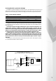
4.5 hydraulic system design
The Midmat HT boilers are designed to operate on a flow to return temperature drop of 20K (∆t 20°C).
Systems must be sealed and pressurised and operate within the range 0.5 bar to 5.3 bar. The system design
should incorporate a pressure gauge, visible from the filling point to indicate the system water pressure.
Table 3 - Boiler hydraulic resistance
Model 220 330
Design Flow Rate at 80/60 Flow/Return Temperatures 2.38 l/s 3.57 l/s
Hydraulic Resistance at 80/60 Flow/Return Temperatures 65.0 kPa 62.5 kPa
Design Flow Rate at 50/30 Flow/Return Temperatures 2.62 l/s 3.95 l/s
Hydraulic Resistance at 50/30 Flow/Return Temperatures 82.5 kPa 74.0 kPa
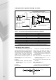
The Signal to start the boiler pump is provided by the boiler, and where the pump motor rating does
not exceed 600 Watt 230V single phase, the pump may be driven directly from power available from the
boiler inbuilt controls.
All systems must be thoroughly cleansed prior to the connection of the boiler. The
system water should be treated to prevent general system corrosion and the
deposition of scale or sludge in the boiler waterways. If installing the boiler onto an old
system, it is recommended to install a spirotech or similar dirt arrester/filter. Failure
to cleanse and water treat the system will render the appliance guarantee void.
If plastic pipes are used for the flow and return pipes, for radiators or under floor
heating, a plate exchanger should be considered between the system water and the
boiler water. If such a separator is not used, the MHS guarantee on all boiler parts will
become null and void, unless it can be proved that the plastic pipes used have a vapour
tight layer.
The connection of the flow and return are located at the top rear of the unit. With regard to servicing,
it is a requirement that isolation valves are installed.
BLR Pump
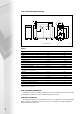
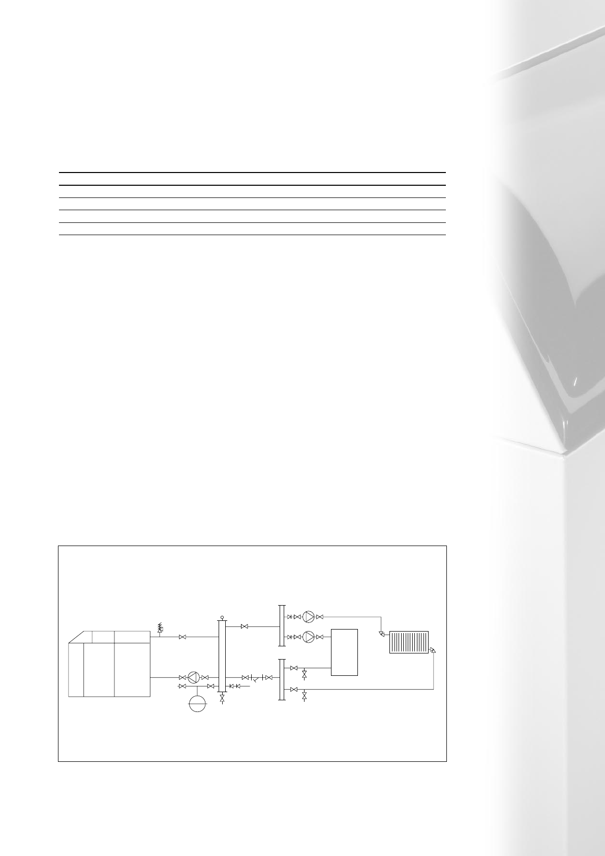
recommended system design
typical single Midmat HT boiler installation
Expansion Vessel
AAV
AAV
AAV
Return Header
Flow Header
Pumps
DOC
DOC
DOC LSV
IV
IV
IV
IV
DOC
SV
Strainer
IV IV
Strata 3 Boiler
Heating Load
IV
IV
IV
IV
IV
IV
HWS
Load
Vertical Low
Velocity Mixing
Header
Vmax 0.5m/s
Fill Point*
Fig 4.5a
* Fill Point. In accordance with BS6644, automatic
pressurisation unit must be installed