
Technical data


23
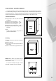
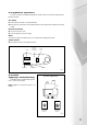
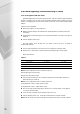
There are 3 options for room temperature:-
● Both circuits, weather variable, without room control influence.
● Room control influence with one room controller for the entire building – must be electrically
connected direct to the boiler. Weiland Plug 4.
● Independent room influence control with 2 room units (one for the radiator circuit – connected
directly to the boiler (Weiland plug 4) and a second room unit for the underfloor circuit connected
to the MR 03 unit).
See section 5.7.5 – Room Unit RE 2132. DIP switch No 1 on the boiler control panel should be set to
ON. If the respective power consumption of pumps 2 and 3 are more than 120W, auxiliary relays (auxiliary
contactors) must be installed.
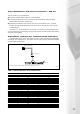
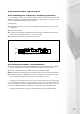
5.8.3 alarm contacts for common fault indication
TheMidimat has a volt free contact, which closes in the case of a fault. This fault contact can be applied
with 230V AC and a maximum of 1A, via an adapter (X9) see fig 5.8f. X9 plug & lead assembly available
from RVR Spare Parts Department.
Fig 5.8f
This contact can be used to trigger an audible or an optical alarm signal in the case of a fault.
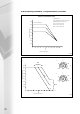
Temperature Resistance Voltage* V Voltage* V
°C Ω Over S1,S4, S5, S7 Over S6, AF
-30 1247 — 1,92
-25 1306 — 1,98
-20 1367 — 2,03
-15 1430 — 2,08
-10 1495 — 2,14
-5 1561 — 2,19
0 1630 1,88 2,24
5 1700 1,93 2,30
10 1772 1,98 2,35
15 1846 2,03 2,40
20 1922 2,08 2,45
25 2000 2,13 2,50
30 2080 2,18 2,55
35 2161 2,22 2,60
40 2245 2,27 —
45 2330 2,32 —
50 2417 2,36 —
55 2506 2,41 —
60 2597 2,45 —
65 2690 2,50 —
70 2785 2,54 —
75 2881 2,58 —
80 2980 2,62 —
85 3080 2,66 —
90 3182 2,70 —
95 3286 2,74 —
100 3392 2,78 —
Table 5 - Sensor temperature versus resistance table
* Measured between both contacts in operation (Sensors are at zero potential against earth)
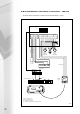
5.8.2 installation and elect connection – MR 03
X9 Plug & Lead
(Part No. 96.00025-0048)
Volt Free Contact
21
21
X9
Control Panel