
Technical data
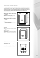

22
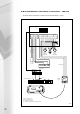
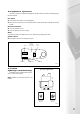
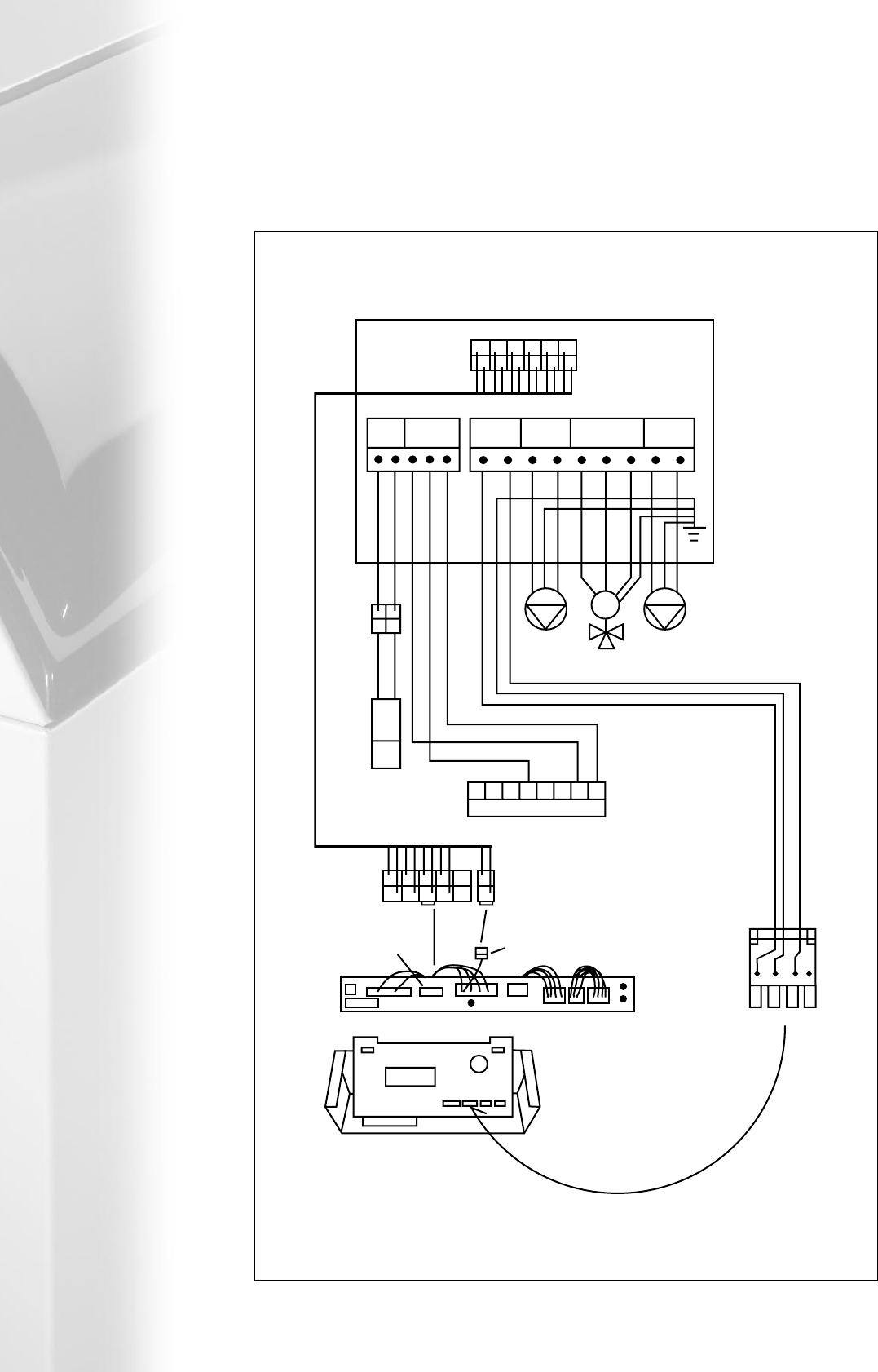
The MR 03 must be connected in accordance with the schematic diagram – fig 5.8e.
5.8.2 installation and elect connection – MR 03
MR 03
X3
X1
1 2 R4 R5 R6 L N
NETZ PUMP 3
PUMP 3
Underfloor
Heating Pump
System
Heating Pump
PUMP 2
SENSOR 7
PUMP 2
L N L1 L2N
M
NL
X2
X4
S7
RE 2132
87654321
X16X3
65
4321
L1 PE N L2
Fig 5.8e
Power Supply
Room unit controlling underfloor
circuit (if fitted)
Weiland
Plug 3
Control Panel Wiring
Pump 2 = Radiator Circuit
Pump 3 = Underfloor Circuit
M = Underfloor mixing valve
S7 = Underfloor circuit mixed flow temperature sensor