
Technical data


14
5.7 electrical connections – general (contd)
L1
PE
A1 A2 R2
R1
NL1
PE
R3
N
N
PE
L1
L2
NPE
L1
Fig 5.7b
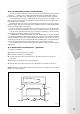
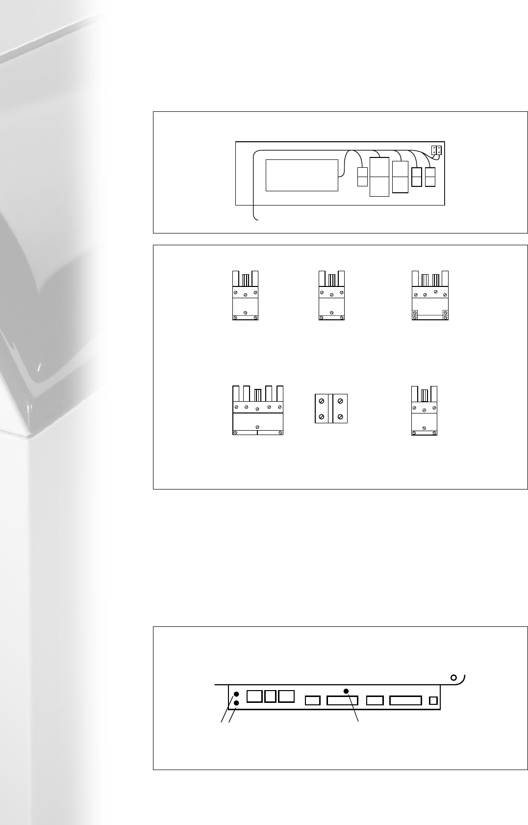
5.7.1 connecting power supply
The mains electrical connection on the Midimat is made via plus No (1) (see fig 5.7b) with a conductor
cross section of 3 x 1.5mm
2
.
Wire used for the outdoor sensor, the room unit and the domestic hot water temperature sensor must
have the minimum cross section, depending upon the cable length stated in table 5, section 4.7.
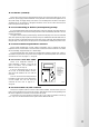
5.7.2 fuses
The Midimat boilers have 3 electrical f uses in the boiler control panel. (fig 5.7b).
1
2
3
x2
Fig 5.7c
location of fuses
64 321
64 321
5
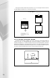
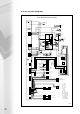
Control Panel Rear Side
location of electrical points
Permanent Supply
(L1 + PE + N)
Outside Air Sensor (A1 + A2)
RE2132 Room Unit (R1 + R2 + R3)
KKM2 Cascade Manager (R2 + R3)
0-10V via an adapter '+' R2 '-' R1
0-3V '+' R2 '-' R1
HWS Sensor
or Thermostat
HWS Diverter Valve or
HWS Primary Pump
(N + PE + L1)
Terminal
Block
External Gas Safety
Shut Off Valve - LPG
Only (if reqd)
(N + PE + L1)
Room
Thermostat/Volt
Free Switch
(L2 + L1)
PR01 / MR03
(N + PE + L1)
weiland plug / socket functions
Phase and Neutral Protection (230 V AC) 5A Fuse 24 V AC 5A Fuse
1 2 3
4
5
6