
Technical data


13
5.6 condensate waste connections
The condensate waste connection is located at the lower rear of the appliance. During the operation
of the boiler , because of the low exhaust gas temperatures in both the heating boiler itselfand in
the exhaust gas system, a slightl y acidic condensation water ( pH value between 3.5 and 5) is deposited.
The condensate waste connection is a 40mm plastic tube located at the rear of the appliance. Only
plastic components must be used for the condensation discharge. Metal pipes are not acceptable due to
the acidic nature of the condensate.
The built in siphon allows the unit to be connected directly to a drain system. A level control device is
built into the siphon. In the event of a blockage in the condensate line, the burner is automatically switched
off before any damage is done to the appliance.
The siphon drain point is located behind the rear casing panel, next to the condensate water
connection. This must be opened annually in order to flush the condense system and to remove any debris.
If any part of the condensate waste pipe is to be run external to the building or is at risk of freezing,
then the pipe must be suitably insulated to protect it from freezing.
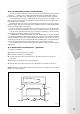
If a suitable drain for accepting the condensate waste is not available nearby to, and below the boiler
(e.g. if the boiler is installed in a basement below ground level), an (optional extra) condensate receptacle
and pump (available from MHS) can be installed adjacent to the appliance. This will collect and remove
condensate to a remote drain up to 5 metres height above the receptacle position. Note that blockage of
the waste discharge will cause the unit to switch off by means of a built in level control device.
It is recommended that the condensate waste pipework should include a method of disconnection and
cleaning points.
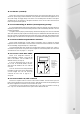
5.7 electrical connections – general
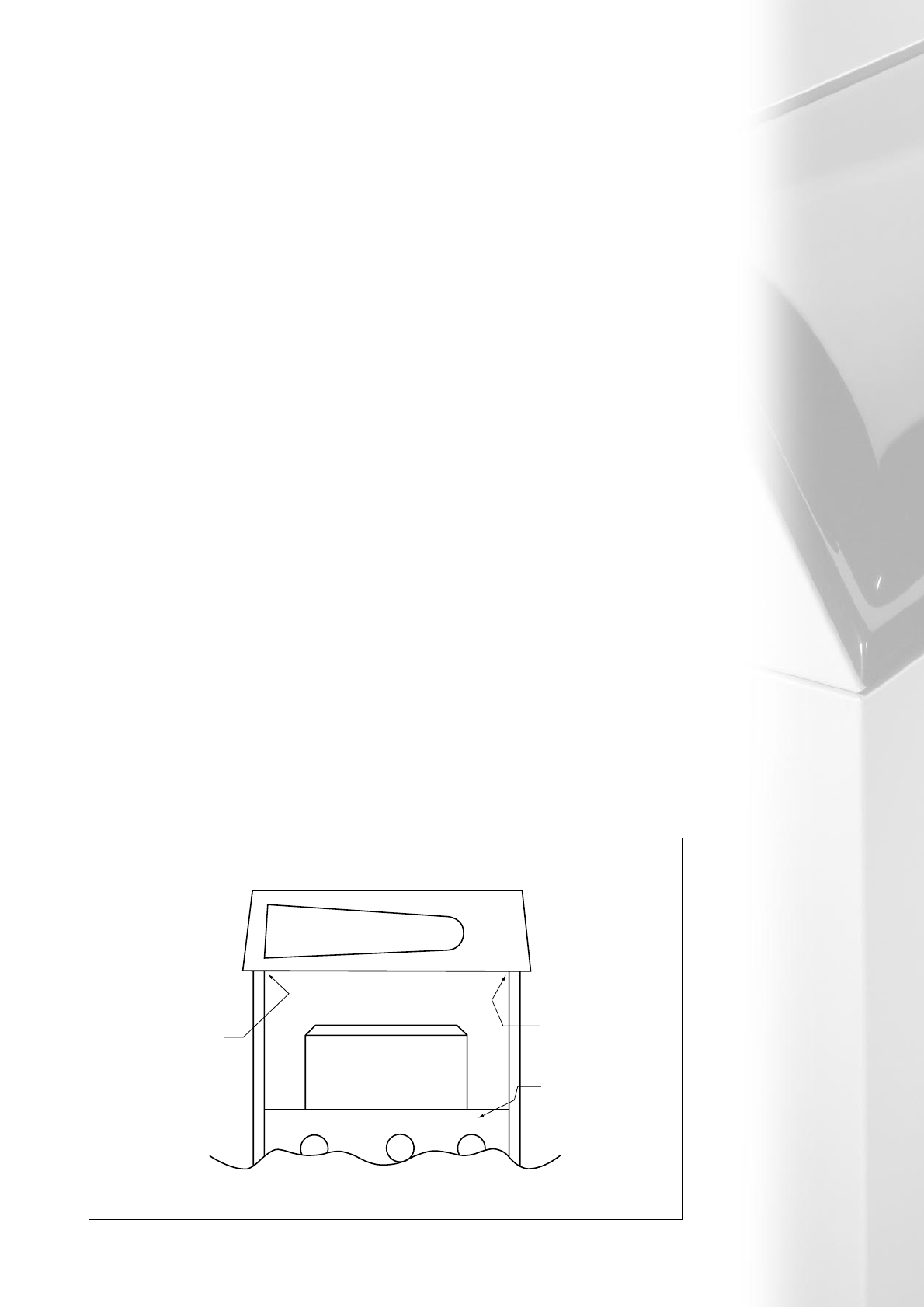
To remove the control panel:-
● Unfasten the screw which secures the front panel.
● Pull the panel out and away from the appliance.
● From inside the casing, remove the 2 fixing screws on the underside, upper return edge of the
2 side panels.
● Slide the entire control panel/box away from the appliance.
● Hang the panel, using the turned up brackets, on to the appliance cross member for easy access.
Note: All electrical connection cables must be fed through from the rear of the boiler. Do not pass cables
through or fix to the casing panels.
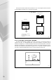
Fig 5.7a
One Screw
One Screw
Casing
Cross
Member