
Technical data


10
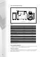
4.5 hydraulic system design (contd)
recommended system design
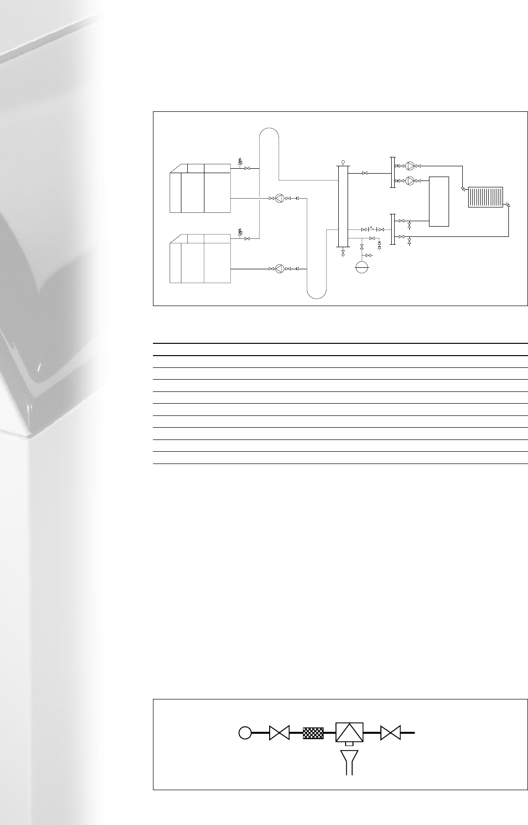
typical multiple Midimat HT boiler installation
Expansion Vessel
AAV
AAV
Return Header
Flow Header
Pumps
DOC
DOC
LSV
IV
IV
IV
IV
NRV
IV
DOC
DOC
SV
Strainer
Strata 3 Boiler
Strata 3 Boiler
Heating Load
IV
IV
IV
IV
IV
IV
IV IV
HWS
Load
Vertical Low
Velocity Mixing
Header
Vmax 0.5m/s
BLR Pump
IV IV
NRV
BLR Pump
SV
Fill Point*
Fig 4.5b
Boiler Power kW Diameter based upon ∆t 20°C
220 100mm
330 125mm
440 125mm
660 150mm
880 175mm
990 175mm
1100 200mm
1320 200mm
1650 225mm
Table 4 - Low velocity vertical mixing header diameter sizing guide
Tube diameters refer to medium grade or large steel tubes and are calculated using data from CIBSE guide C4
AAV
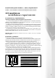
* Fill Point. In accordance with BS6644, automatic
pressurisation unit must be installed
The initial filling of a sealed heating system, and
subsequent refilling, must be by a method that has
been approved by the Water Regulation Advisory
Scheme (WRAS) for that type of heating system.
ie. Non Domestic (Other than in-House) Fluid
Category 4 (C-4). For Category 4 systems, the
approved method of filling must comprise of the
following components in the arrangement shown;
● Control valve
● Strainer
● Verifiable backflow device with reduced
pressure zone (RPZ Valve). Incorporating a
'Type BA' air gap.
● Tundish
● Control valve
Further more, in accordance with BS6644, for
boiler/s with an input greater than 60kW, an
automatic pressurisation unit must be installed to
automatically replenish any lost or evpourated water.
The pressurisation unit must comprise of the
following components;
● A cistern fitted with a float operated valve
incorporating either a 'Type AG' (C-3), or
'Type AF' (C-4) air gap.
● A presssure booster pump fitted with a single
check valve
● A pressure reducing valve
● A pressure switch
For information on a comprehensive range of
pressurisation units please contact MHS Sales.
4.6 filling the system
MCWS
CV CV
Strainer
Heating System
Tundish
RPZ