
Technical data
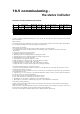

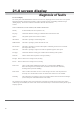
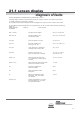


Table Of Contents
- User Instructions for the Micromat boiler
- Product Description
- Technical Data
- Delivery Consignment / Unpacking the boiler
- Boiler location
- Installation Clearances
- Wall Mounting
- Gas Connection
- Gas Conversion
- System Flow & Return connections
- Condensate Connection
- Flue / Combustion Air connection
- Flue Systems
- Calculating Flue Resistance
- Ventilation requirements single appliances
- Hydraulic System Design
- System type 1
- System type 2
- System type 3
- System type 4
- System type 5
- System type 6
- System type 7
- System type 8
- Water Treatment
- Soldering Flux
- Electrical Connection
- System Type 1
- System Type 2
- System Type 3
- System Type 4
- System Type 5
- System Type 6
- System Type 7
- System Type 8
- Commissioning The Micromat EC
- Installation Codes
- First Firing
- Pop Up Menu
- Setting DHW Temperature
- Servicing
- Screen Display Diagnosis of Faults

56
21.0 screen display
diagnosis of faults
2.1 Screen display
The control panel of the MICROMAT EC boiler has an LCD screen, displaying two lines of data. This screen provides
information about the operation of the appliance; it shows operation messages (non flashing) and fault messages
(flashing display). The first line contains text information about the status of the unit.
It shows:
STATUS MESSAGES (NON FLASHING) FOR NORMAL OPERATION
Standby No heat demand (boiler not required to be on)
Pre-purge Combustion chambers are being pre-ventilated with air from the burner fans
Ignition The ignition sequence of the burners is initiated
CH Demand The boiler is operating in central heating mode
DHW Demand The boiler is operating to produce domestic hot water
Flue-emission The boiler is operating in test mode at mid output to enable flue gas emissions to be checked
(auto expires after 10 mm)
10min Low The boiler is operating in engineers test mode for adjustment purposes (auto expires
Post-purge Combustion chambers are being post-ventilated with air following boiler operation
Limit F/R The flow and/or return temperature is too high (currently)
Fan high The lower burner fan is running too fast (currently)
Fan low The lower burner fan is running too slow (currently)
Fault room u There is a fault with the modulating unit (RE 132) or Cascade manager (KKM2) or a
fault in the wiring to these controls (in these circumstances the boiler runs continuously
in heating mode to protect the building)
Fault outside There is a fault in the outside air sensor or in the wiring to the sensor or the dip switches are
incorrectly set to ask the boiler to look for an outside sensor when there is none installed
Deaerating The in built pumps are operating to remove any possible collection of air from the heat exchangers.
(Occurs when power turned off/on and after reset of fault)
The second line of text displays values such as temperature, percentages etc and the red reset button may be used to
scroll through (for information) the values of the various sensors that are/may be connected in the boiler plus fan speeds
and pump speed etc.