
Technical data
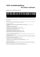

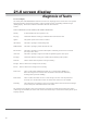
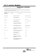


Table Of Contents
- User Instructions for the Micromat boiler
- Product Description
- Technical Data
- Delivery Consignment / Unpacking the boiler
- Boiler location
- Installation Clearances
- Wall Mounting
- Gas Connection
- Gas Conversion
- System Flow & Return connections
- Condensate Connection
- Flue / Combustion Air connection
- Flue Systems
- Calculating Flue Resistance
- Ventilation requirements single appliances
- Hydraulic System Design
- System type 1
- System type 2
- System type 3
- System type 4
- System type 5
- System type 6
- System type 7
- System type 8
- Water Treatment
- Soldering Flux
- Electrical Connection
- System Type 1
- System Type 2
- System Type 3
- System Type 4
- System Type 5
- System Type 6
- System Type 7
- System Type 8
- Commissioning The Micromat EC
- Installation Codes
- First Firing
- Pop Up Menu
- Setting DHW Temperature
- Servicing
- Screen Display Diagnosis of Faults
at k) If dirt has deposited on the fan blades, each blade must be carefully cleaned, until the blade material is
visible
again. If this is not done evenly the fan will not rotate properly and be out of balance.
at I) Carefully bend the electrode without touching the burner, until the correct distance has been reached
IMPORTANT NOTE
IF ANY WATER CARRYING JOINT WITHIN THE BOILER IS DISASSEMBLED THEN THE “0” RING
SEAL MUST ALWAYS BE REPLACED, LIKEWISE IF ANY OTHER SEAL IS NOTED TO BE DEFORMED
THEN THEY SHOULD ALSO BE REPLACED.
WATER SEALING “0” RINGS ARE A ONE TIME USE ONLY AND SHOULD NOT BE RE-USED.
Cancelling the Service Message
Following the maintenance operations, the service message (when displayed) must be cancelled. This is done by
pressing and holding in the service button for at least 10 seconds.