
Technical data
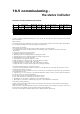

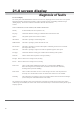
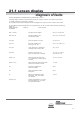


Table Of Contents
- User Instructions for the Micromat boiler
- Product Description
- Technical Data
- Delivery Consignment / Unpacking the boiler
- Boiler location
- Installation Clearances
- Wall Mounting
- Gas Connection
- Gas Conversion
- System Flow & Return connections
- Condensate Connection
- Flue / Combustion Air connection
- Flue Systems
- Calculating Flue Resistance
- Ventilation requirements single appliances
- Hydraulic System Design
- System type 1
- System type 2
- System type 3
- System type 4
- System type 5
- System type 6
- System type 7
- System type 8
- Water Treatment
- Soldering Flux
- Electrical Connection
- System Type 1
- System Type 2
- System Type 3
- System Type 4
- System Type 5
- System Type 6
- System Type 7
- System Type 8
- Commissioning The Micromat EC
- Installation Codes
- First Firing
- Pop Up Menu
- Setting DHW Temperature
- Servicing
- Screen Display Diagnosis of Faults
18.6 setting domestic
hot water temperature
A) With HWS sensor in/on calorifier
Press and hold the menu/reset button on the boiler conbtrol panel for over 3 seconds. Next press the ‘+’
key until [temp DHW] appears on the display. Press the menu/reset button to enter adjustment mode. Press the
‘+’ or ‘-’ key to adjust the setpoint. The maximum temperature temperature setting is 60°C.
B) With cylinder thermostat in/on DHW calorifier
Set desired stored hot water temperature by the adjustment of the cylinder thermostat. With this
arrangment time control of hot water charging is possible by installing a time switch in series with the cylinder
thermostat, but hot water charging always takes priority over the heating demand.
18.7 output for charging
hot water
There is no adjustment necessary or possible, as the boiler controls are self learning and will self adapt the
optimum output to hot water according to the heat transfer capabilities of the connected hot water calorifier or
cylinder.
19.0 setting the boiler
to work
1. To fit casing to boiler ensure hooks on top rear edge of boiler case engage properly into rear chassis assembly.
Latch bottom case fixings and tighten central locking screw.
2. Turn ON on/off switch and set any external controls to auto operation.
3. Set ECO/ECO plus option to ECO position for systems without additional heating circuit pump OR Set
ECO/ECO plus switch to ECO plus position for systems with a local low velocity header and additional heating
circuit pump.
4. With boiler operating (burners on) press “Test” button on boiler control panel to test overheat controls in the
boiler. The boiler must shut-down and then re-ignite.
20.0 servicing
instruction
GENERAL
In general, maintenance/inspections should take place:
a) When the display on the unit indicates that inspection is required (status shows [SERVICE]).
b) At least every 18 months, before carrying out any maintenance the unit must be inspected.