
Technical data
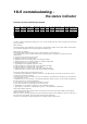


Table Of Contents
- User Instructions for the Micromat boiler
- Product Description
- Technical Data
- Delivery Consignment / Unpacking the boiler
- Boiler location
- Installation Clearances
- Wall Mounting
- Gas Connection
- Gas Conversion
- System Flow & Return connections
- Condensate Connection
- Flue / Combustion Air connection
- Flue Systems
- Calculating Flue Resistance
- Ventilation requirements single appliances
- Hydraulic System Design
- System type 1
- System type 2
- System type 3
- System type 4
- System type 5
- System type 6
- System type 7
- System type 8
- Water Treatment
- Soldering Flux
- Electrical Connection
- System Type 1
- System Type 2
- System Type 3
- System Type 4
- System Type 5
- System Type 6
- System Type 7
- System Type 8
- Commissioning The Micromat EC
- Installation Codes
- First Firing
- Pop Up Menu
- Setting DHW Temperature
- Servicing
- Screen Display Diagnosis of Faults
18.5 commissioning -
the status indicator
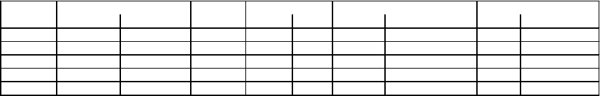
Overview of fan revolutions per minute
Start Revs
Min. rev/min Max. Rev/min Rev/min Rev/min [%] Rev/min [%] of max. HC Rev/min [%] of max. HC
EC 11/22 900 6000 2200 3000 100 1380 46 900 30
EC 15/22 900 6000 2200 4080 100 1380 33 900 22
EC 23/28 900 6000 2200 4680 100 1380 29 900 19
EC 31/36 900 6000 2200 4860 100 1380 28 900 18
EC 40 H 1260 6300 2200 6300 100 1380 22 1260 19
Min. Boiler absolute
Boiler type
Boiler Absolute Max HK?? Min. Boiler standard
in case of a boiler controlpanel exchange (EC 11/22 - EC 40) the Revs per min. should correspond to the back-up
panel instructions.
Status Indicator
The status indicator gives information in clear text on the operating condition of the boiler. Status reports appear
as non flashing messages and fault reports appear as flashing text.
Status report (non flashing)
The following status reports are given during normal operation of the micromat EC
1. [No Demand] The burner is switched off and the circulating pump is operating in accordance with heat
requirements.
2. [Pre-Purge] The fan is purging the burner.
3. [Ignition] The gas/air mix is being fired.
4. [Heating] burner and circulating pumps are heating the system
5. [Storage] burner and/or circulating pumps are heating strorage water.
6. [Post-Purge] the fan is purging the burner.
7. [Legionella] tha anti-Legionella program is active.
8. [S/D] The boiler is in Summer mode / day mode (heating up stage)
9. [S/N] The boiler is in Summer mode / night mode.
10. [W/D] The boiler is in Winter mode / day mode (heating up stage)
11 [W/N] The boiler is in Winter mode / Night mode (cooling down stage)
The following status reports are exceptions to these:
1. [Service] A yearly maintenance must be carried out on the Micromat EC. The boiler will continue to work as
normal when this display is showing.
2. [Fault M. Ru]???? The connection to the room unit is broken. The Micromat EC will heat to the recommended
room temperature of 20°C.
3. [Fault M. ET]???? The connection to the external temperature sensor is broken. In this instance the Micromat
EC will heat as for a 0°C external temperature.
4. [Fan High] The boiler fan revolutions per minute are too high
5. [Fan Low] The boiler fan revolutions per minute are too low.
6. [Deaeration]???? The boiler is undergoing a short ventilation program.
7. [Limit F/R]???? The boiler is experiencing a high flow / return temperature momentarily.
Fault Report (flashing indicator)
A table of fault reports and possible sources of the faults can be found in the section entitles ‘Screen display /
Diagnosis of faults’ on pages _____
When the source of the error has been found and corrected the report must be deleted by using the ‘reset’ key. If
the fault occurs again,please contact the RVR Customer Care Department.
The boiler is locked when the status display shows a flashing indicator (fault report).