
Technical data


Table Of Contents
- User Instructions for the Micromat boiler
- Product Description
- Technical Data
- Delivery Consignment / Unpacking the boiler
- Boiler location
- Installation Clearances
- Wall Mounting
- Gas Connection
- Gas Conversion
- System Flow & Return connections
- Condensate Connection
- Flue / Combustion Air connection
- Flue Systems
- Calculating Flue Resistance
- Ventilation requirements single appliances
- Hydraulic System Design
- System type 1
- System type 2
- System type 3
- System type 4
- System type 5
- System type 6
- System type 7
- System type 8
- Water Treatment
- Soldering Flux
- Electrical Connection
- System Type 1
- System Type 2
- System Type 3
- System Type 4
- System Type 5
- System Type 6
- System Type 7
- System Type 8
- Commissioning The Micromat EC
- Installation Codes
- First Firing
- Pop Up Menu
- Setting DHW Temperature
- Servicing
- Screen Display Diagnosis of Faults
48
18.3 first
firing
Notes
The MICROMAT EC boiler has a single heat exchange
and burner assembly. There is one gas valve serving
the assembly.
a) Ensure gas & electricity supplies are turned on to
the appliance.
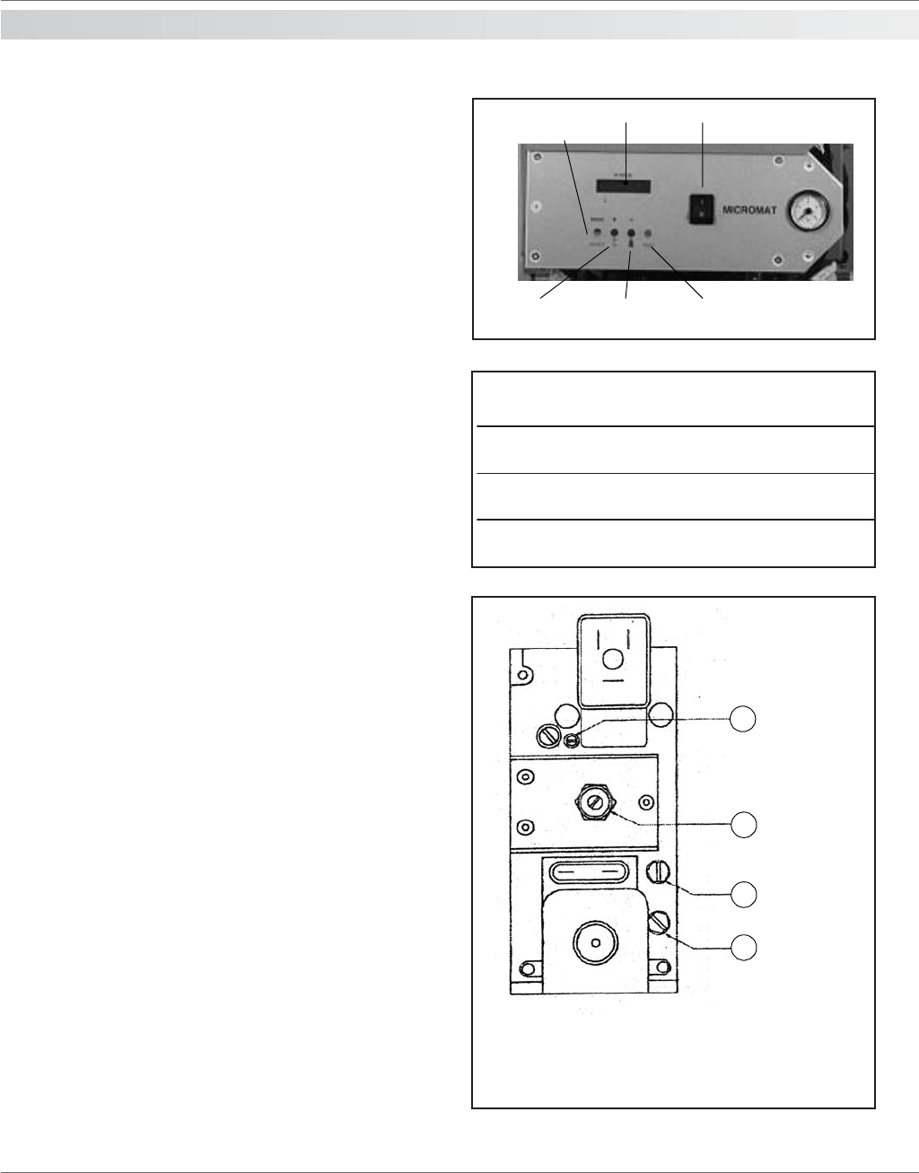
b) Switch on the boiler at the on/off switch. (See figure
to the right) The appliance will purge the combustion
chamber with air from the burner fan and then will pulse
the pumps on/off (deaerating).
c) Attach U tube manometer to inlet pressure test point
on gas valve (See figure 8). The nominal pressure
should be 20mb for NG or 37mb for LPG.
d) Press the Engineers test button twice - the screen
should/must display [10 min Low]. To reduce the burner
to its lowest firing rate press the ‘-’ key until the fan
speed reduces to its minimum revs (see section 18.5).
In the event that ignition of the burner does not occur
after 4 attempts the appliance will go to ignition failure
lockout. Remove the cover cap screws from Qmin
adjustment on gas valve (See figure 8(3)) turn
adjustment screw half turn clockwise.
Press reset button, appliance will post purge and vent
again.
Press Engineers test button twice to reset appliance to
“I0 min Low” and ignition sequence will start again. If
ignition fails again after 4 attempts, then further increase
Qmin on gas valve by half turn until burner ignites.
e) Observe the colour of burner flame - correct colour
should be dull red. Adjust colour of burner flame using
Qmin until flame colour is correct. Following this
procedure will avoid poisoning your combustion
analyser.
f)Remove flue gas analysis test point cap or plug (from
top right of combustion chamber) of the heat exchanger
and insert probe of combustion analyser Adjust as
necessary Qmin of valve to obtain required C02% value.
(See table 2) Make adjustments slowly and wait at least
2 minutes for reading to stabilise before re-adjusting.
Remove analyser and refit cap/plug to test point.
NOTE: Test period expires after 10 minutes - if this
expires whilst commissioning is still in progress, press
Engineers button twice to reset and carry on with
necessary checks and adjustments. To exit “10 min Low’
test period - press Engineers button once, this will set
controls to auto.
g)Press the ‘+’ button until the fan is at its maximum
rate (see section 18.5) This will set the burner to
maximum output.
Display ON/Off switch
Menu/Reset
Button
Summer/Winter
and “+” button
Test button
Engineers
and “-” button
4
3
2
1
Q max
Q min
Burner offset
pressure test
point
Gas inlet
pressure test
point
Adjustments
Turning 3 clockwise increases min output & CO2%
Turning 4 clockwise increase max output & CO2%
epytsaG02GsaGtaN13GGPL
tuptuOniMta%2OC5.9-921-11
tuptuOxaMta%2OC2.9-7.811-01
Flue Gas CO
2
% Settings
Figure 8