
Technical data


Table Of Contents
- User Instructions for the Micromat boiler
- Product Description
- Technical Data
- Delivery Consignment / Unpacking the boiler
- Boiler location
- Installation Clearances
- Wall Mounting
- Gas Connection
- Gas Conversion
- System Flow & Return connections
- Condensate Connection
- Flue / Combustion Air connection
- Flue Systems
- Calculating Flue Resistance
- Ventilation requirements single appliances
- Hydraulic System Design
- System type 1
- System type 2
- System type 3
- System type 4
- System type 5
- System type 6
- System type 7
- System type 8
- Water Treatment
- Soldering Flux
- Electrical Connection
- System Type 1
- System Type 2
- System Type 3
- System Type 4
- System Type 5
- System Type 6
- System Type 7
- System Type 8
- Commissioning The Micromat EC
- Installation Codes
- First Firing
- Pop Up Menu
- Setting DHW Temperature
- Servicing
- Screen Display Diagnosis of Faults
40
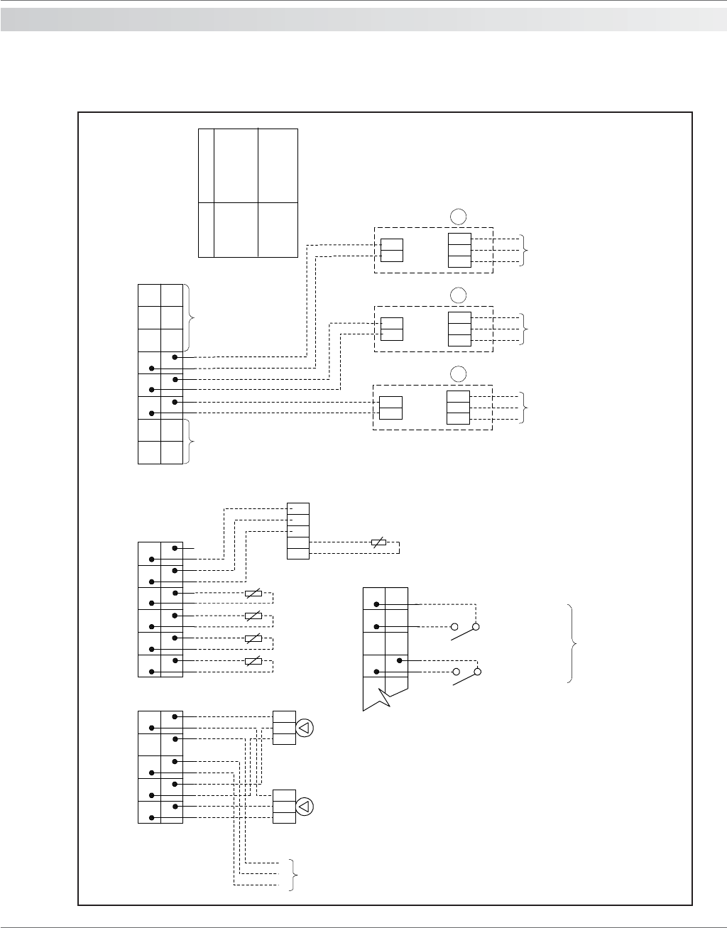
17.0 electrical
connections
Typical electrical connection schematic to suit system type 6
13579
10
642
11 13 15 17 19
20
161412 18 22
21 23 25 27 29 31
32
282624 30 34
33
36 38
35 37
X1 X2 X4
L
N
PE
L
N
PE
L
N
PE
4 3 2 5 1
RE2132
Modulating
Room unit
*
* QAW44 optional
Remote Sensor
GND
PMW
+24V
15 17 19
2016
18 22
21
X2
Not Used
Additional
Boilers
R2
R3
L
N
PE
Boiler
No. 1
R2
R3
L
N
PE
Boiler
No. 2
R2
R3
L
N
PE
Boiler
No. 3
Supply
230V
Supply
230V
Supply
230V
111
NOTE: No connections
other than those shown
are to be made to the
boilers.
Alternative External
Control Options
* Cylinder Stat / HWS
Time Switch
* External Controls for
Heating Circuit
* HWS Primary
Pump 230V 2A
Max
* Heating Circuit
Pump 230V 2A
Max
* - If Required
Supply
230V
R2 and R3 on boiler
upper terminal switch
Installation code
Cascaded boiler (KKM
2) installation without
DHW sensor or with
DHW control via
thermostat and three
way valve
35
71
Description
Cascaded boiler (KKM
2) installation with
DHW sensor and
pumped DHW circuit.