
Technical data


Table Of Contents
- User Instructions for the Micromat boiler
- Product Description
- Technical Data
- Delivery Consignment / Unpacking the boiler
- Boiler location
- Installation Clearances
- Wall Mounting
- Gas Connection
- Gas Conversion
- System Flow & Return connections
- Condensate Connection
- Flue / Combustion Air connection
- Flue Systems
- Calculating Flue Resistance
- Ventilation requirements single appliances
- Hydraulic System Design
- System type 1
- System type 2
- System type 3
- System type 4
- System type 5
- System type 6
- System type 7
- System type 8
- Water Treatment
- Soldering Flux
- Electrical Connection
- System Type 1
- System Type 2
- System Type 3
- System Type 4
- System Type 5
- System Type 6
- System Type 7
- System Type 8
- Commissioning The Micromat EC
- Installation Codes
- First Firing
- Pop Up Menu
- Setting DHW Temperature
- Servicing
- Screen Display Diagnosis of Faults
Energy Technology
Ltd.
33
16.1 water treatment
system cleaning
The entire system must be thoroughly cleansed and flushed to remove debris, flux residues etc before opening the
boiler isolation valves & flooding the boiler. Particular care must be taken where the MICROMAT EC boiler is being
retro-fitted into an old/existing system, as system silt or magenite can be very damaging to the new boiler.
The system must be filled with clean chemically neutral water. Water hardness must not exceed 3.6 mol/m
3
(=20°dH).
Chloride Concentrations must not exceed 150mg/l.
Following cleansing and flushing, the system must be dosed with a good quality water treatment to prevent corrosion
and the formation of scale. A suitable corrosion inhibitor ‘INIBAL’ is available from RVR Limited and should be used
in all systems. The required concentration is 1-2% of system capacity.
Failure to observe these requirements will render the guarantee on the product void.
Cleansing, flushing and water treatment must be carried out in accordance with the requirements of BS 7593:1992.
16.2 care with the use of
soldering flux
The MICROMAT EC boiler has heat exchangers fabricated from 316L stainless steel. It is most important that the
compatibility of any flux is checked with the flux supplier before use, and that any flux manufacturers recommendations
are strictly followed with regards to use in conjunction with stainless steel.
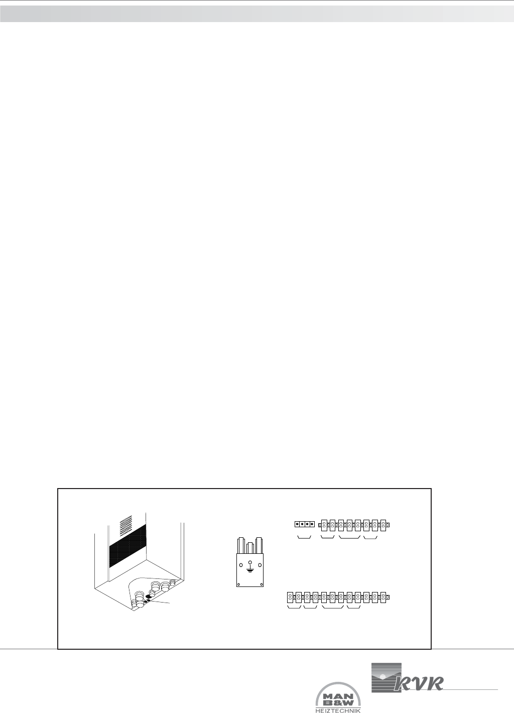
The electrical connections to the MICROMAT EC boiler are made via a Weiland Plug and socket (incoming live,
neutral and earth) and two terminal blocks which are located within the boiler case and below the control panel. The
lower terminal block is 24V d.c. and the upper terminal block is 220V a.c.
Connections must only be made using appropriate diameter multi strand flex cables and cable entry must only be
via the rubber glanded cable entry points located at the bottom rear r/h side of the appliance. If the boiler is to be
room sealed flued then care must be taken to ensure the cable entries are reasonably air tight.
For electrical connection plug/socket & terminal function and location see fig below.
17.0 electrical
connection
Cable
glands
1 2 3 4 R1 R2 R3 5 6
L1 N L1 N L2 L1 N
Front Terminal Block
DHW
Sensor
Outside Air
Sensor
RE2132
Not Used
External gas
valve or external
pump
Earth
MR03 and/
or Room
thermostat
2way 3port
mixing valve
or storage
water pump
Back Terminal Block
Wieland plug no. 1 -
Incoming Power
NL1
PE