
Technical data


Table Of Contents
- User Instructions for the Micromat boiler
- Product Description
- Technical Data
- Delivery Consignment / Unpacking the boiler
- Boiler location
- Installation Clearances
- Wall Mounting
- Gas Connection
- Gas Conversion
- System Flow & Return connections
- Condensate Connection
- Flue / Combustion Air connection
- Flue Systems
- Calculating Flue Resistance
- Ventilation requirements single appliances
- Hydraulic System Design
- System type 1
- System type 2
- System type 3
- System type 4
- System type 5
- System type 6
- System type 7
- System type 8
- Water Treatment
- Soldering Flux
- Electrical Connection
- System Type 1
- System Type 2
- System Type 3
- System Type 4
- System Type 5
- System Type 6
- System Type 7
- System Type 8
- Commissioning The Micromat EC
- Installation Codes
- First Firing
- Pop Up Menu
- Setting DHW Temperature
- Servicing
- Screen Display Diagnosis of Faults
Energy Technology
Ltd.
29
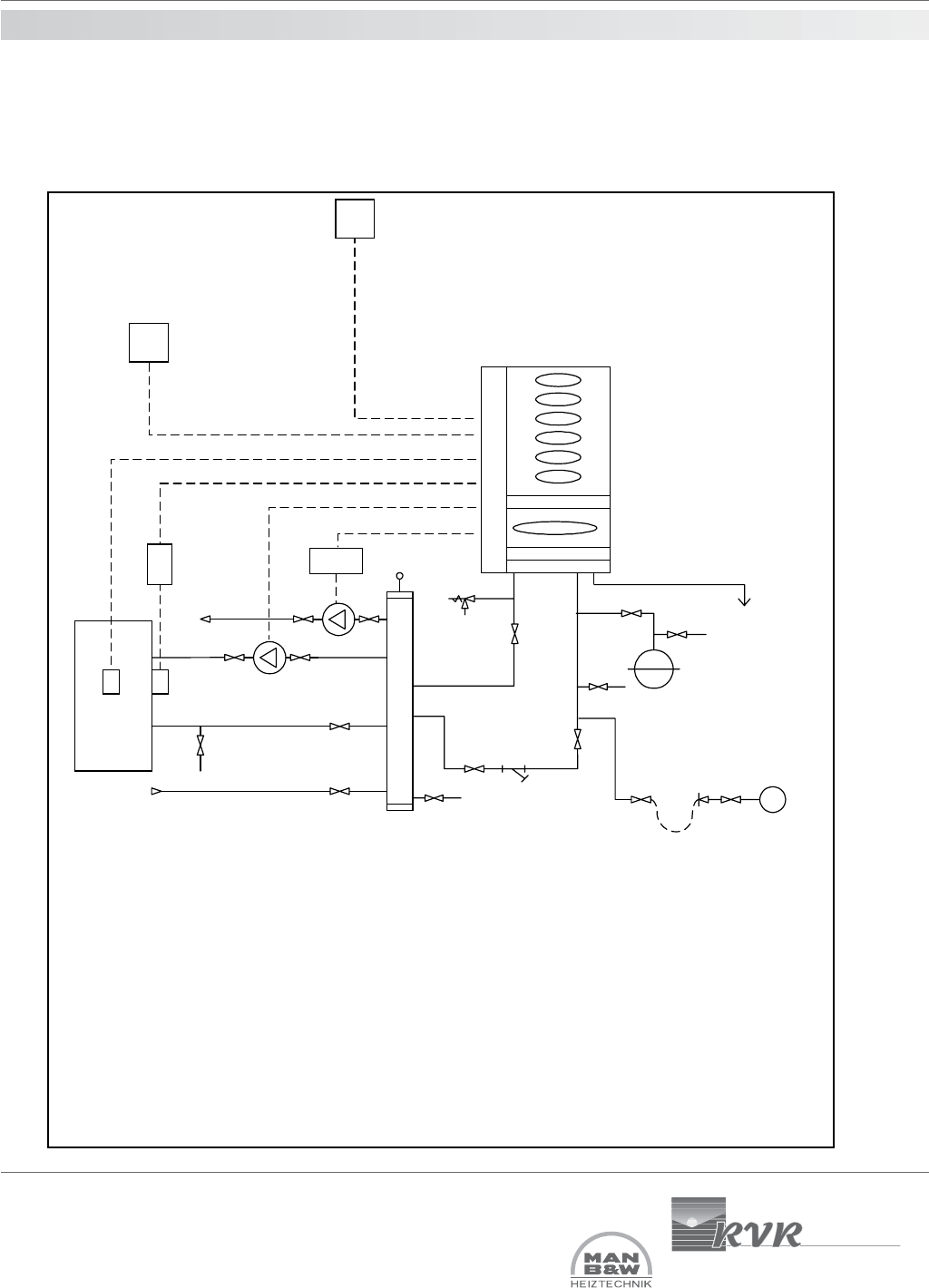
16.0 hydraulic system
design
OS = Outside air temperature sensor, used where direct-on-boiler weather
compensated flow temperatures are required.
C = Room temperature controls e.g. RE2132 modulating room unit from RVR Ltd.,
or, separated time clock & room thermostat.
S = HWS sensor from RVR Ltd. Gives 24hr HWS operation
W/T = Alternative to “S” where “W” is a time switch in series with a cylinder
thermostat “T”. Allows for timed HWS.
PR01= Pump regulation module from RVR Ltd. Allows heating pump to be driven
from boiler, providing for auto operation, frost protector running & summer standstill
exercising.
Must be used where RE2132 modulating room unit is installed. Max pump motor
load 2A.
System type 5
Typical Single MICROMAT EC boiler installation serving heating & domestic hot water with hot water priority. Hot
water & heating circuits both have index resistance exceeding 1 metre & are served by independent pumps from a
low velocity mixing header. Heating flow temperature may be fixed/constant or weather variable.
Condensate
Micromat EC
boiler
LSV
DOC
Expansion Vessel
Safety Valve
CWM
IV
IV
Strainer
AV
Low velocity mixing header
Max. velocity 0.5m/s
OS
C
PRO 1
DOC
IV
DOC
Calorifier
TS
W
IV
IV
system circuits
Return from
system circuits
Flow to
DOC
HWS Primary
Pump Max 1A