
Technical data


Table Of Contents
- User Instructions for the Micromat boiler
- Product Description
- Technical Data
- Delivery Consignment / Unpacking the boiler
- Boiler location
- Installation Clearances
- Wall Mounting
- Gas Connection
- Gas Conversion
- System Flow & Return connections
- Condensate Connection
- Flue / Combustion Air connection
- Flue Systems
- Calculating Flue Resistance
- Ventilation requirements single appliances
- Hydraulic System Design
- System type 1
- System type 2
- System type 3
- System type 4
- System type 5
- System type 6
- System type 7
- System type 8
- Water Treatment
- Soldering Flux
- Electrical Connection
- System Type 1
- System Type 2
- System Type 3
- System Type 4
- System Type 5
- System Type 6
- System Type 7
- System Type 8
- Commissioning The Micromat EC
- Installation Codes
- First Firing
- Pop Up Menu
- Setting DHW Temperature
- Servicing
- Screen Display Diagnosis of Faults
Energy Technology
Ltd.
27
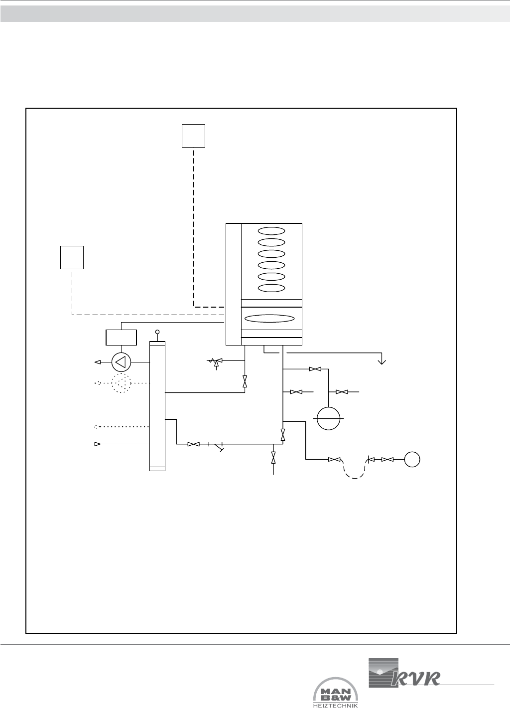
16.0 hydraulic system
design
OS = Outside air temperature sensor, used where direct-on-boiler weather
compensated flow temperatures are required.
C = Room temperature controls e.g. RE2132 modulating room unit from RVR Ltd.,
or, separated time clock & room thermostat.
PR01 = Pump regulation module from RVR Ltd. Allows heating pump to be driven
from boiler, providing for auto operation, frost protector running & summer standstill
exercising.
Must be used where RE2132 modulating room unit is installed. Max pump motor
load 2A.
System type 3
Typical Single MICROMAT EC boiler installation serving heating only and using a low velocity mixing header
where system index resistance exceeds 1 metre. Flow temperature may be fixed/constant or weather variable.
Condensate
Micromat EC
boiler
LSV
IV
DOCDOC
Expansion Vessel
Safety Valve
CWM
IV
IV
Strainer
Flow to
system circuits
Return from
system circuits
DOC
AAV
Low velocity mixing header
Max. velocity 0.5m/s
OS
C
PRO 1