
Technical data


Table Of Contents
- User Instructions for the Micromat boiler
- Product Description
- Technical Data
- Delivery Consignment / Unpacking the boiler
- Boiler location
- Installation Clearances
- Wall Mounting
- Gas Connection
- Gas Conversion
- System Flow & Return connections
- Condensate Connection
- Flue / Combustion Air connection
- Flue Systems
- Calculating Flue Resistance
- Ventilation requirements single appliances
- Hydraulic System Design
- System type 1
- System type 2
- System type 3
- System type 4
- System type 5
- System type 6
- System type 7
- System type 8
- Water Treatment
- Soldering Flux
- Electrical Connection
- System Type 1
- System Type 2
- System Type 3
- System Type 4
- System Type 5
- System Type 6
- System Type 7
- System Type 8
- Commissioning The Micromat EC
- Installation Codes
- First Firing
- Pop Up Menu
- Setting DHW Temperature
- Servicing
- Screen Display Diagnosis of Faults
Energy Technology
Ltd.
25
16.0 hydraulic system
design
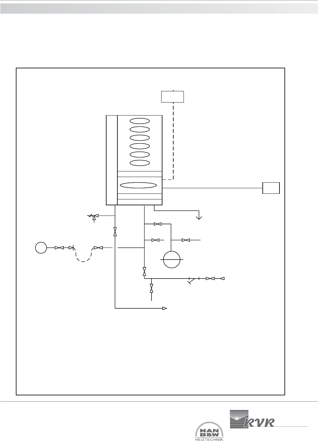
System type 1
Typical Typical Single MICROMAT EC boiler installation serving heating only where the boiler’s own in-built circulating
pump is used to circulate the water around the system (used only where system index resistance <1 metre). Flow
temperature may be fixed/constant or weather variable.
Condensate
Micromat EC
boiler
IV
Safety Valve
Flow to
system
OS
C
LSV
DOC DOC
CWM
IV
IV
Strainer
Return from
system
DOC
Expansion Vessel
OS = Outside air temperature sensor, used where
direct-on-boiler weather compensated flow
temperatures are required.
C = Room temperature controls e.g. RE2132
modulating room unit from RVR Ltd., or,
separate time clock & room thermostat.