
Technical data


Table Of Contents
- User Instructions for the Micromat boiler
- Product Description
- Technical Data
- Delivery Consignment / Unpacking the boiler
- Boiler location
- Installation Clearances
- Wall Mounting
- Gas Connection
- Gas Conversion
- System Flow & Return connections
- Condensate Connection
- Flue / Combustion Air connection
- Flue Systems
- Calculating Flue Resistance
- Ventilation requirements single appliances
- Hydraulic System Design
- System type 1
- System type 2
- System type 3
- System type 4
- System type 5
- System type 6
- System type 7
- System type 8
- Water Treatment
- Soldering Flux
- Electrical Connection
- System Type 1
- System Type 2
- System Type 3
- System Type 4
- System Type 5
- System Type 6
- System Type 7
- System Type 8
- Commissioning The Micromat EC
- Installation Codes
- First Firing
- Pop Up Menu
- Setting DHW Temperature
- Servicing
- Screen Display Diagnosis of Faults
Energy Technology
Ltd.
21
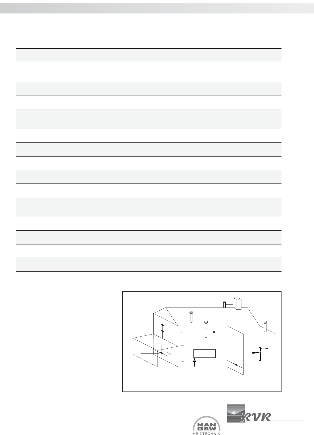
flue terminal positions
The flue terminal of a MICROMAT EC boiler
will plume heavily and care must be taken
when selecting a terminal position to ensure
that a ‘nuisance situation’ is not created.
If a flue terminal is positioned within 2 m
above ground level or any upper part of a
building where people have general access
(e.g. balcony etc) then the terminal should
be fitted with an appropriate guard.
noisnemiD noitisoPlanimreT delaeSmooReulFdecnalaB delaeSmooRnoN
A
,kcirbria,gnineponawolebyltceriD
.cteswodniw
dednemmoceRtoN
mm003
mm003
B
niardrosepiplios,srettugwoleB
sepip
mm57 mm57
CsevaewoleBmm002mm002
D
.foortropracroseinoclabwoleB
dednemmoceRtoN
mm002
tonnoitallatsnituB
dednemmocer
mm002
tonnoitallatsnituB
dednemmocer
EepipliosroepipniardlacitrevmorFmm57mm57
F renroclanretxerolanretninamorF mm003 mm003
G
rofoorgnitcesretni,dnuorgevobA
levelynoclab
mm003mm003
H lanimretehtgnicafecafrusamorF mm0002 mm0002
IlanimretehtgnicaflanimretamorFmm0002mm0002
J
.g.e(tropracehtnignineponamorF
gnillewdotni)wodniw,rood
mm0021
tonnoitallatsnituB
dednemmocer
mm0021
tonnoitallatsnituB
dednemmocer
K
emasehtnolanimretamorfyllacitreV
llaw
mm0051mm0051
L
ehtnolanimretamorfyllatnoziroH
llawemas
mm003 mm003
M
silanimretehthcihwnollawehtmorF
detnuom
a/nmm05
N foorehtnoerutcurtslacitrevamorF mm005 mm005
PfoorhtiwnoitcesretnievobAmm005mm005
14.0 calculating flue resistance-
flue pressure loss
Minimum dimensions of flue terminal positions see fig. 7 below
A
G
F
D
H,I
J
E
A
G
B,C
P
P
N
P
L
K
L
K
F
F
Fig 7