
Technical data

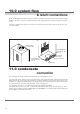
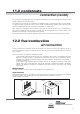


Table Of Contents
- User Instructions for the Micromat boiler
- Product Description
- Technical Data
- Delivery Consignment / Unpacking the boiler
- Boiler location
- Installation Clearances
- Wall Mounting
- Gas Connection
- Gas Conversion
- System Flow & Return connections
- Condensate Connection
- Flue / Combustion Air connection
- Flue Systems
- Calculating Flue Resistance
- Ventilation requirements single appliances
- Hydraulic System Design
- System type 1
- System type 2
- System type 3
- System type 4
- System type 5
- System type 6
- System type 7
- System type 8
- Water Treatment
- Soldering Flux
- Electrical Connection
- System Type 1
- System Type 2
- System Type 3
- System Type 4
- System Type 5
- System Type 6
- System Type 7
- System Type 8
- Commissioning The Micromat EC
- Installation Codes
- First Firing
- Pop Up Menu
- Setting DHW Temperature
- Servicing
- Screen Display Diagnosis of Faults
20
14.0 calculating flue resistance-
flue pressure loss
example I
A MICROMAT EC 62 boiler is installed with a concentric
flue system which takes an all horizontal route to a wall
terminal. Length of flue = 3m including one 90° bend.
Resistance =
3 x 1m length 70/125 concentric tube @ 16.6 Pa = 49.8
1 x 90° 70/125 concentric bend @ 16.6 Pa =16.6
I x 70/125 concentric wall terminal @ 21.4 Pa = 21.4
Total Resistance = 87.6Pa
conclusion: Total resistance is less than 100 Pa. therefore,
no alternative design required and no effect on boiler output,
or positioning required
example 2
A MICROMAT EC 45 boiler is installed with a concentric
flue system which takes a part horizontal, part vertical route
to a roof terminal with rain cap.
Length of horizontal section = 1m, vertical section = 6m,
system includes 1 x 90
o
bend.
Resistance =
7 x 1m lengths 70/125 concentric tube @ 10.7 Pa = 74.9
1 x 90° 70/125 concentric bend @ 10.7 Pa= 10.7
1 x 70/125 roof terminal @ 21.9 Pa = 21.9
Total Resistance = 107.5 Pa
Take into account that 6m of vertical (assume uninsulated,
as air for combustion direct from outside air surrounds the
flue gas tube) flue creates 10 Pa of up-draught,
then final resistance = 107.5 - 10 = 97.5 Pa.
conclusion: Final operating resistance is less than 100 Pa,
therefore, no alternative design required and no effect on
boiler output.
example 3
A MICROMAT 1-75 boiler is installed (non room sealed) with
a proposed flue using DN 70 PPS single skin flue compo-
nents which takes a part horizontal, part vertical route to a
vertical open termination with bird mesh.
Length of horizontal section = 4m, length of vertical
(uninsulated) section = 11m with 4 x 90
o
bends,
and 2 x 45
o
bends.
Resistance =
15 x 1m lengths DN 70 PPS tube @ 21.4 Pa = 321
4 x 90
o
DN 70 PPS bends @ 21.4 Pa = 85.6
2 x 45
o
DN 70 bends @ 10.7 Pa = 21.4
1 x DN 80 open termination @ 15.6 Pa = 15.6
Total Resistance: 443.6 Pa
Take into account that 11m of vertical uninsulated flue
creates 18 Pa of up-draught, then final resistance would be
443.6-18 = 425.6 Pa.
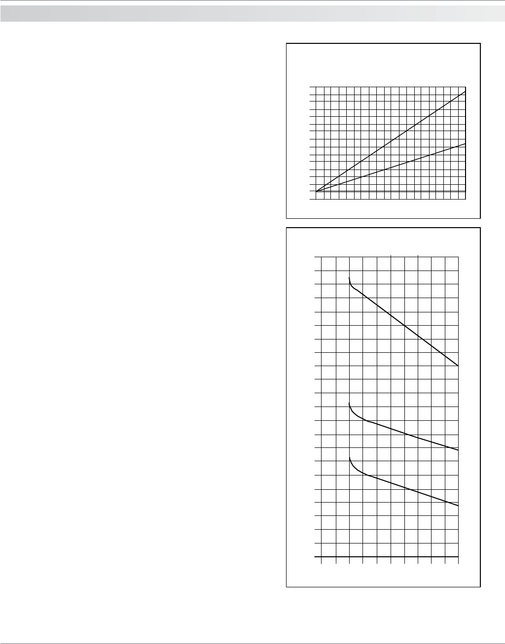
Reference to the graph of resistance effect on boiler output
shows the output would be reduced to approximately 59kW.
If this is unacceptable, then the flue resistance must be re-
calculated using a larger size flue tube as shown below or
consideration given to moving the boiler position.
Re-calculating proposed flue installation using DN 100.
15 x 1m lengths DN 100 PPS tube @ 3.0 Pa = 45
4 x 90
o
DN 100 bends @ 3.0 Pa = 12
2 x 45
o
DN 100 bends @ 1.5 Pa = 3.0
1 x DN 100 open termination @ 4.0 Pa = 4.0
Total Resistance: 64 Pa
Take into account thermal up-draught created (as before)
18 Pa. Therefore operating resistance = 64 – 18 = 46 Pa,
with no effect on boiler output.
140
130
120
110
100
90
80
70
60
50
40
30
20
10
0
0 2 4 6 8 101214161820 2224262830323436 3840
Vertical Flue Lengths - metres
Draught - Pa
29
31
33
35
37
39
41
45
47
49
51
53
55
57
59
61
63
65
67
69
71
73
43
0 50 100 150 200 250 300 350 400 450 500
Flue System resistance - Pa
MICROMAT EC76
MICROMAT EC 62
MICROMAT EC 45
thermal updraught when
flue gas temp 80°C and outside temp -5°C
A = Insulated or within the building
B = Uninsulated and exterior to the
building
effect of flue system resistance
on boiler output
Boiler output kW at: flow 80°C Return 60°C
A
B