
Technical data

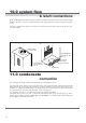
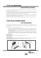
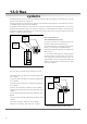

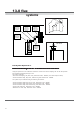

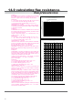
Table Of Contents
- User Instructions for the Micromat boiler
- Product Description
- Technical Data
- Delivery Consignment / Unpacking the boiler
- Boiler location
- Installation Clearances
- Wall Mounting
- Gas Connection
- Gas Conversion
- System Flow & Return connections
- Condensate Connection
- Flue / Combustion Air connection
- Flue Systems
- Calculating Flue Resistance
- Ventilation requirements single appliances
- Hydraulic System Design
- System type 1
- System type 2
- System type 3
- System type 4
- System type 5
- System type 6
- System type 7
- System type 8
- Water Treatment
- Soldering Flux
- Electrical Connection
- System Type 1
- System Type 2
- System Type 3
- System Type 4
- System Type 5
- System Type 6
- System Type 7
- System Type 8
- Commissioning The Micromat EC
- Installation Codes
- First Firing
- Pop Up Menu
- Setting DHW Temperature
- Servicing
- Screen Display Diagnosis of Faults

Energy Technology
Ltd.
19
.)aP(ecnatsiseRtnenopmoC ledoMrelioB
22/6182/4263/1354/83
lanimreTllaWcirtnecnoC521/07 6 5.8 6.01 7.21
paCniaRtuohtiWlanimreTfooRcirtnecnoC521/0765.8
6.017.21
paCniaRhtiWlanimreTfooRcirtnecnoC521/07 9.8 7.21 8.51 91
ebuTcirtnecnoC52I/07htgnelmI5.44.69.75.9
dneBcirtnecnoC52I/07C°39 5.4 4.6 9.7 5.9
dneBcirtnecnoC52I/07C°544.24.32.45
sageulFgniyrraCebuTSPP07NDhtgnelmI 4 7.5 1.7 5.8
noitsubmoCgniyrraCebuTSPP07NDhtgnelmI
riA
4.24.32.45
sageulFgniyrraCdneBSPP07ND°09 4 7.5 1.7 5.8
riAnoitsubmoCgniyrraCdneBSPP07ND°094.24.32.45
sageulFgniyrraCdneBSPP07ND°54 2 8.2 4.3 4
riAnoitsubmoCgniyrraCdneBSPP07ND°5414.17.12
07NDpaCyenmihCdelaeSmooR 6.5 8 01 21
riArosageulF-eceiPresaercnISPP001x07ND8.01.13.15.1
sageulFgniyrraCdneBSPP001ND°09 7.1 4.2 3 5.3
riAnoitsubmoCgniyrraCdneBSPP001ND°092.17.11.25.2
sageulFgniyrraCdneBSPP001ND°54 8.0 1.1 3.1 5.1
riAnoitsubmoCgniyrraCdneBSPP001ND°548.01.13.15.1
sageulFgniyrraCebuTSPP001NDhtgnelmI 8.0 1.1 3.1 5.1
noitsubmoCgniyrraCebuTSPP001NDhtgnelmI
riA
8.01.13.15.1
hseMhtiWnoitanimreTnepO07ND 4.3 8.4 9.5 7
hseMhtiwnoitanimreTnepO001ND8.01.13.15.1
resaercnIcirtnecnoC051/001oT521/07 4.1 2 5.2 3
sageulFgniyrraCdneBSPP001ND°096.08.09.00.1
riAnoitsubmoCgniyrraCdneBSPP001ND°09 6.0 8.0 9.0 0.1
sageulFgniyrraCdneBSPP001ND°546.08.09.00.1
riAnoitsubmoCgniyrraCdneBSPP001ND°54 3.0 4.0 5.0 5.0
sageulFgniyrraCebuTSPP001NDhtgnelmI8.01.13.15.1
14.0 calculating
flue resistance
The excess pressure available for overcoming the frictional resistance of a flue system is 100 Pa. The table below
of flue component resistances will assist the designer in calculating total flue system frictional loss.
If the total installed flue system resistance exceeds 100 Pa., then the result will be a reduction in boiler output.
Reference to the ‘Effect of Flue System Resistance On Boiler Output”, graphs will assist. If the resistance of a
proposed flue system has an unacceptable effect on boiler output, then a larger diameter flue tube should be
selected.
Thermal up-draught is generated in a vertical flue system, reducing the resistance of the system. Reference to the
‘Thermal Up-draught Graph’ will provide a figure in Pa., which may be deducted from the total calculated flue system
resistance.
NB. Thermal up-draught does not apply to horizontal sections of a flue system.