
Technical data

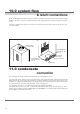
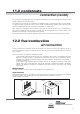
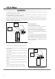

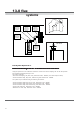

Table Of Contents
- User Instructions for the Micromat boiler
- Product Description
- Technical Data
- Delivery Consignment / Unpacking the boiler
- Boiler location
- Installation Clearances
- Wall Mounting
- Gas Connection
- Gas Conversion
- System Flow & Return connections
- Condensate Connection
- Flue / Combustion Air connection
- Flue Systems
- Calculating Flue Resistance
- Ventilation requirements single appliances
- Hydraulic System Design
- System type 1
- System type 2
- System type 3
- System type 4
- System type 5
- System type 6
- System type 7
- System type 8
- Water Treatment
- Soldering Flux
- Electrical Connection
- System Type 1
- System Type 2
- System Type 3
- System Type 4
- System Type 5
- System Type 6
- System Type 7
- System Type 8
- Commissioning The Micromat EC
- Installation Codes
- First Firing
- Pop Up Menu
- Setting DHW Temperature
- Servicing
- Screen Display Diagnosis of Faults
Energy Technology
Ltd.
15
If any part of the condensate pipe is to be run external to the building or is at risk of freezing, then the pipe must be
suitably insulated to protect from freezing.
If a suitable drain for accepting the condensate is not available nearby to, and below the boiler (e.g. boiler installed
in a basement below ground level location), then a suitable condensate sump receptacle with a discharge pump
should be installed below the boiler to remove the condensate to a remote drain.
When making the condensate pipe connection to the boiler, do not use adhesives, it is recommended to
lightly apply a suitable jointing tape (PTFE or similar) and use only light pressure to connect fittings to the
appliance to avoid damage to the condensate outlet assembly.
It is recommended that the condensate pipework should include a method of disconnection and cleaning points.
11.0 condensate
connection (contd.)
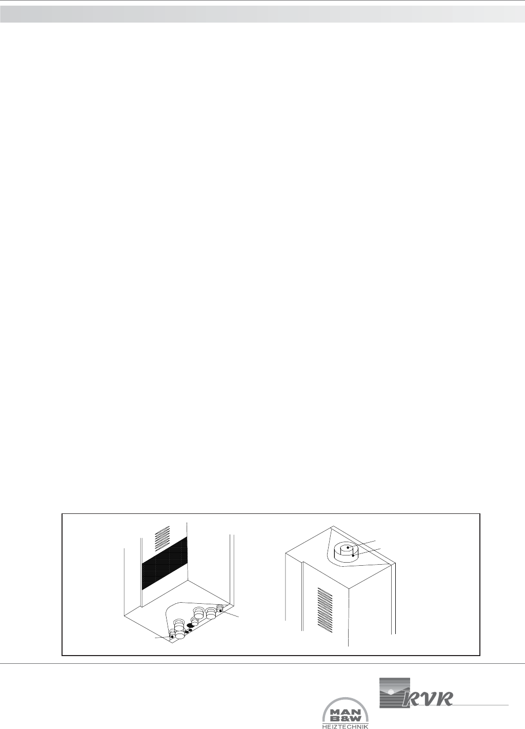
12.0 flue/combustion
air connection
The flue connection and combustion air inlet to the appliance are located on the top of the appliance, see fig 6.
These connections are arranged concentrically with the 70mm flue gas connection centrally within the 125mm air
inlet connection.
There are two options for flueing the MICROMAT EC boiler.
i) Conventionally, using flue gas tube only and air for combustion from the room or compartment in which the
appliance is installed. If using a conventional flue arrangement then the room or compartment must be
ventilated in accordance with the requirements of BS 6644 or BS5440 as appropriate. For guidance on
ventilation see section 15.
ii) Room sealed using concentric 70/125 components where air for combustion is taken from outside of the
building. When using a room sealed flue, where air for combustion is provided from outside of the building
directly to the appliance, ventilation to a compartment may still be required - See section 15 for general
space cooling.
Multiple Boilers
For detail and advice on common flues serving multiple boilers, contact RVR Ltd.
Important Note
Where the MICROMAT EC is to be installed in an application where the combustion air is likely to be contaminated
with oxidising agents, such as swimming pool areas, special industrial processes etc, then the
appliance must be room sealed.
Air Intake (70mm)
Exhaust (125mm)
Condensate
Connection
Condensate
Connection
Fig 5 Fig 6