
Technical data

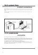
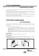
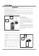

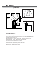

Table Of Contents
- User Instructions for the Micromat boiler
- Product Description
- Technical Data
- Delivery Consignment / Unpacking the boiler
- Boiler location
- Installation Clearances
- Wall Mounting
- Gas Connection
- Gas Conversion
- System Flow & Return connections
- Condensate Connection
- Flue / Combustion Air connection
- Flue Systems
- Calculating Flue Resistance
- Ventilation requirements single appliances
- Hydraulic System Design
- System type 1
- System type 2
- System type 3
- System type 4
- System type 5
- System type 6
- System type 7
- System type 8
- Water Treatment
- Soldering Flux
- Electrical Connection
- System Type 1
- System Type 2
- System Type 3
- System Type 4
- System Type 5
- System Type 6
- System Type 7
- System Type 8
- Commissioning The Micromat EC
- Installation Codes
- First Firing
- Pop Up Menu
- Setting DHW Temperature
- Servicing
- Screen Display Diagnosis of Faults

14
10.0 system flow
& return connections
11.0 condensate
connection
The condensate connection is located at the underside rear of the appliance see fig 5.
The condensate syphon cleaning point is factory fitted with a heavy grade black plastic cap which MUST NOT BE
REMOVED (see fig 5) apart from routine maintenance cleaning operations and must be in place whenever the
appliance is in operation. WARNING operating the appliance with the cap removed from the syphon cleaning point
will cause products of combustion to be discharged from the cleaning point.
The condensate connection is a ¾” BSP Male threaded stub fabricated from plastic.
The installer must connect to this stub, a ccondensate pipe fabricated from plastic tube and fittings (¾”, 22mm,
overflow pipe is considered suitable). Copper Tube is not acceptable. The condensate pipe must fall continuously
from the appliance to suitable nearby drain.
NOTE: The MICROMAT EC boiler must only be installed on sealed and pressurised systems. The maximum working
pressure of the boiler = 3 bar. It is recommended that the final working pressure (hot) of the system does not exceed
2.3 bar.
The boiler is equipped with a 22mm flow connection on the left (when looking head on at the boiler) and one return
on the right (22mm).
Air Intake (70mm)
Exhaust (125mm)
Flow Connection
Return Connection
Flow DHW/Storage
Connection (EC...HS
& EC...S)
Return DHW/Storage
Connection (EC...HS
& EC...S)
Condensate
Connection
fig 3
fig 4