
Technical data

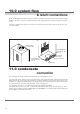
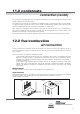
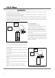

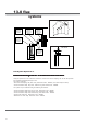

Table Of Contents
- User Instructions for the Micromat boiler
- Product Description
- Technical Data
- Delivery Consignment / Unpacking the boiler
- Boiler location
- Installation Clearances
- Wall Mounting
- Gas Connection
- Gas Conversion
- System Flow & Return connections
- Condensate Connection
- Flue / Combustion Air connection
- Flue Systems
- Calculating Flue Resistance
- Ventilation requirements single appliances
- Hydraulic System Design
- System type 1
- System type 2
- System type 3
- System type 4
- System type 5
- System type 6
- System type 7
- System type 8
- Water Treatment
- Soldering Flux
- Electrical Connection
- System Type 1
- System Type 2
- System Type 3
- System Type 4
- System Type 5
- System Type 6
- System Type 7
- System Type 8
- Commissioning The Micromat EC
- Installation Codes
- First Firing
- Pop Up Menu
- Setting DHW Temperature
- Servicing
- Screen Display Diagnosis of Faults
12
The MICROMAT EC boiler mounts to the wall via a wall
mounting bracket which interlocks to a rail mounted on the
rear of the boiler. The wall mounting bracket should be firmly
fixed to the wall using suitable fixings with a countersunk
head. The wall mounting bracket positioning detail is shown
in fig 1. The boiler must be carefully offered up to the wall
so that the rail on the rear of the boiler is just above the
wall mounting bracket and then the boiler should be lowered
to engage the bracket and rail. Lifting is advised with 2
persons. Do NOT lift the boiler by the internal parts of the
appliance.
important
When viewed from the side, the north/south axis of the
boiler must be vertical. The appliance must not be inclined
out from the top, if necessary block or shim behind the
bottom rear of the boiler to achieve a vertical installation.
8.0 wall
mounting
The gas connection is located at the base of the appliance
rear r/h side, see fig 2.
The pipe size used to supply the appliance must not be
smaller than the gas connection size on the appliance.
The connection to the appliance must include a suitable
method of disconnection and a gas control cock must be
installed adjacent to the appliance for isolation purposes.
The gas pipe used to supply the appliance must not allow a
pressure drop of greater than 1mbar from the meter to the
appliance.
The nominal inlet working gas pressure measured at the
appliance should be 20.0 mbar for Nat Gas
(G20) or 37 mbar for LPG (G31).
9.0 gas
connection
∅
12
2x35x12
458
945
785 115 45
165 165
Gas
Connection