
Technical data


36
STRATA2
(Prog#) Description of Prog# Range Preffered Setting
LPB communication setting
140 LPB control device address 0..16 1
0 Standalone single RVA 47
1 Master RVA 47 cascade manager with sensors attached
2…16 Slave RVA 47s operating from master RVA 47
(ie House No.) (Each subsequent RVA 47 should be
given consecutive numbers)
141 LPB control segment addres 0..14 0
0 Heat generator (ie Street name)
1….14 Heat consumer
142 LPB Bus power supply 0..1 1
0 Off
1 On
143 Operation of LPB power supply On/Off – –
144 Display of LPB communication On/Off – –
145 Change over via LPB connection 0..1 1
0 All controllers in same segment
1 All controllers in LPB system
146 Summer/Winter change over function 0..1 0
0 Local control only
1 Entire control via LPB
147 Central Standby switching 0..1 0
0 Deactivated
1 Activated
148 Clock mode 0..3 2
0 Autonomous Clock Individual controller
can have different times
1 System time, time will match system
cannot be adjusted
2 Systems time with adjustment
3 System clock, master.
There can only be one master on system
Input H1
170 Operation of H1 terminals 0..4 0
0 Changeover of operation when switch is made.
(DHW stopped)
1 Changeover of operation when switch is made.
(DHW released)
2 Minimum flow temperature maintained (set at 171)
3 Heat generation stopped when switch is made.
(Frost Active)
4 0-10 Volt control to vary flow temperature.
(Curve set at 172)
171 Minimum temperature set point for H1 8..95 80
172 Maximum temperature set point for H1 5…130 82
173 Operating action of H1 control contacts 0..1 1
0 The contact is normally closed
1 The contact is normally open
The RVA 47 will operate according to its internal time switches and presets. If a remote BMS is
controlling the RVA 47 via a Volt Free switch across H1 ‘0’ should be inserted.
This will allow the boilers to operate when the Volt Free switch is made and stopped (blocked), when
the switch is opened.
If you are controlling the lead (master) RVA/Boiler via a volt free switch across H1, all slave modules
should be left with ‘1’ as the input. This will allow the AUTO light and the OFF light to indicate their
operational mode dictated by the lead (master) RVA/Boiler.
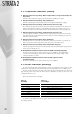
Table 11
7.2 heating engineer parameter setting (contd)