
Technical data


31
STRATA2
3
2
1
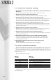
gas valve
Q max
Q min
Burner offset
pressure
test point
Adjustments
Turning 2 clockwise increases min output & CO
2
%
Turning 3 Anti clockwise increases max output & CO
2
%
6.4.2 setting maximum load
The correct CO
2
combustion on low fire should now have been achieved. To set the maximum load:
● Press the ‘Chimney Sweep’ button a second time, the letter ‘H’ will appear in the display and the unit
will begin to operate at maximum capacity.
Again check the combustion figures.
● If the CO
2
content is below the stated figure, increase the gas throughput by turning the adjusting screw
(3) counter-clockwise.
● If the CO
2
content is above the stated figure decrease the gas throughput by turning the adjusting screw
(3) clockwise.
● Pressing the ‘Chimney Sweep’ button a third time will return the unit to automatic mode, and the
display will show the flow temperature.
Note: Adjusting the high fire, has a marked effect on the low fire figures, whereas adjusting the low fire
has little effect on the high fire figures.
It is therefore suggested that once the initial set-up has been carried out, a check is made of the two
settings before returning the unit to complete automatic operation.
6.4.3 setting maximum/minimum load
for upper module
Repeat operations described in 6.4.1 and 6.4.2 – but applied to the upper module.
6.5 setting for propane gas
To set the unit for propane gas, complete the following steps:
● Disassemble the gas pipe between the gas valve and the gas air pipe.
● Install a propane nozzle with a diameter of 7mm on the outlet of the gas valve.
● Reconnect the gas pipe.
To obtain the correct capacity, the combustion fan speed must be adapted for propane gas, by placing
the DIP switch 8 in the ON position.
Fig 6.4a
6.4.1 setting
minimum load
To set the minimum load refer to figure 6.4a and
follow the instructions below:
● Press the ‘Chimney Sweep’ button once, the
letter ‘L’ will appear in the display and the unit
will commence operation at minimum capacity,
for up to 10 minutes.
● Check the combustion figures with those
stated above.
● If the CO
2
content is below the stated figure,
increase the gas throughput by turning the
adjusting screw (2) clockwise.
● If the CO
2
content is above the stated figure,
decrease the gas throughput by turning the
adjusting screw (2) counter-clockwise.