
Technical data


18
STRATA2
5.0 installation
intructions
5.1 unpacking the boiler
The boiler is delivered in a palletted carton containing the boiler and associated fittings, plus any other
optional ancillary flue or control components in separate cartons.
The boiler carton contains:
● Fully assembled boiler.
The Strata 2-120 is also delivered with the following items:
● User manual and operating instructions.
● Installation and Servicing instructions for the Engineer.
Built into each unit are the following:
● A gas stop cock for each heat module.
● Three way return water cut-off.
● RVA 47 control unit (master and slave boilers), 1 outside air sensor, 1 flow sensor and 1 return sensor.
The unit must be inspected immediately after delivery. Any damage to the consignments must be
reported within 3 days.
To unpack the boiler, carefully cut away the outer packaging and open the carton top. Lift off the
bottomless carton. By holding the chassis only lift the appliance away from the palette.
To remove the casing from the boiler:
● Remove the two screws on the bottom front edge of the top casing panel.
● Remove panel to the front.
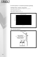
5.2 positioning the boiler
Move the appliance to the desired location, making sure that all clearance dimensions as stated in
section 3.2 are adhered to. Level the appliance in a vertical position by turning the adjustable feet
underneath the base of the unit. Check that the appliance is in a true vertical position by using a spirit level.
Once the appliance is in a true vertical position, the adjustable feet must be secured by locking the nuts.
5.3 air supply and exhaust connections
The unit has two connections, one for the supply of combustion air and the other for the discharge of
the products of combustion. Each connection is clearly labelled and located at the rear top of the appliance.
5.4 gas connection
The Gas connection is located at the rear of the appliance. The gas supply should be sized, installed,
tested and purged in accordance with IGE/UP/1&2.
The connection to the appliance must include a suitable method of disconnection and a gas control
cock must be installed adjacent to the appliance for isolation purposes.
The gas pipe used to supply the appliance must not allow a pressure drop of greater than 1 mbar from
the meter to the appliance. The nominal inlet working gas pressure measured at the appliance should be
20.0 mbar for Nat Gas (G20). The installer should install a pressure test point adjacent to the gas inlet
connection. The gas supply line should be purged.
WARNING: Before purging open all doors and windows, also extinguish any cigarettes, pipes and any
other naked lights.