
Technical data


14
STRATA2
Additional Notes for Room Sealed Appliances:
The Clean Air Act Memorandum prevents the use of balanced flue appliances discharging at low level
where the total heat input to the plant room exceeds 150kW. Where the Clean Air Act does not prevent
installation, the following rules must be applied.
Note: Detailed recommendations for flue installation are given in BS5440:1
The following points are for general guidance:
● The boiler must be installed so that the terminal is exposed to external air.
● It is important that the position of the terminal allows free passage of air across it at all times.
● It is essential to ensure that products of combustion discharging from the terminal cannot re-enter the
building or any other adjacent buildings, through ventilators, windows, doors, other sources of natural
air infiltration, or forced ventilation/air conditioning.
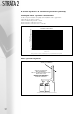
● The minimum acceptable dimensions from the terminal to obstructions and ventilation openings are
specified in figure 4.3e.
● If the terminal discharges into a pathway or passageway check that combustion products will not cause
nuisance and that the terminal will not obstruct the passageway.
● Where the lowest part of the terminal is fitted less than 2m (78ins) above ground, above a balcony
or above a flat roof to which people have access, the terminal MUST be protected by a purpose
designed guard.
● Where the terminal is fitted within 850mm (34ins) of a plastic or painted gutter, or 450mm (18ins)
of painted eaves, an aluminium shield at least 750mm long must be fitted to the underside of the
painted surface.
● The air inlet/flue outlet duct MUST NOT be closer than 25mm (1in) to combustible material.
Note: Under most weather conditions the terminal will emit a plume of steam. This is normal but
positions where this would cause a nuisance should be avoided.
In the case of horizontal flue gas discharge pipes, an angle of 3º must be observed in the direction of
the boiler (5.0cm for every metre of pipe length) with a fall towards the boiler, to allow condense in the
flue gases to return to the unit.
Minimum dimensions of flue terminal positions:
flue terminal positions
H,I
J
P
A
G
F D
E
A
G
P
B,C
F
F
L
K
L
K
P
N
4.3 flue options & terminal position (contd)