
- Modern Home Products Corporation Indoor Fireplace User Manual

10
Vermont Castings EWF36A
20005167
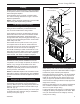
The size of the hole in ceiling will vary with the angle at
which the chimney passes through ceiling.
Drive a nail up through ceiling at marked chimney
center point. Go to oor above and see where hole
will be cut. Check to see where existing ceiling joists
and other possible obstructions are located...i.e. wiring,
plumbing etc... If necessary, re-position chimney and/or
replace to avoid obstructions.
Cover replace collar opening and cut proper sized
chimney hole in chimney.
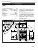
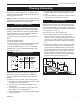
Frame the ceiling chimney hole as shown in Figure
10. It is good practice to use framing lumber that is the
same size as the ceiling joists; this is a requirement at
attic level.
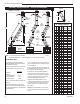
The following table gives restop spacer model num-
bers:
FP551b
17 1/2"
Framing chimney hole
5/13/99 djt
Existing
Ceiling
Joists
17¹⁄₂”
(445mm)
17¹⁄₂”
(445mm)
Chimney
Hole
Ceiling
New Framing
Members
FP551b
Typical frame for ceiling chimney hole.
The of the frame the same
as the hole size selected from Figure 9 in order to
provide required the 2” (51mm) air space between the
outside diameter of the chimney and the edges of the
framed ceiling hole.
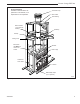
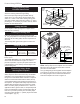
Slide replace into position.
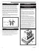
Safety strips are used to ensure that any combustible
materials in front of the replace are protected even
though a noncombustible hearth extension is required.
When the nished extended hearth is added, the top
of the nished hearth must be ush with the bottom of
the replace. “Z” shaped metal safety strips have been
supplied with the replace and are required for instal-
lation. The safety strips provided have a 1” offset. For
applications with a greater offset, “Z” shaped strips will
have to be fabricated of metal. Overlap safety strips at
least 1/2” to provide a positive joint. The safety strips
must also extend at least 1¹⁄₂” (38mm) beyond the sides
of the replace. (Fig. 11)
Safety strips are not required over noncombus-
tible oors where all supports at the base of the re-
place are noncombustible.
Two (2) nailing anges are supplied with the replace.
To level the box and secure it rmly in place, remove
the nailing anges from the hearth and install at the
sides of the replace as shown in Figure 12.
WF557
BR
11/10/97
“Z” Metal Safety
Strips (1 or 2 pcs.)
“Z” Safety
Strip
Hearth Ext.
Fire-
place
Plat-
form
FP557b
1¹⁄₂”
(38mm)
1/2” Min.
Overlap
Safety strip installation.
Decorative
Hearth
Face
Angle of Chimney at Ceiling
Size of Chimney Vertical 30°
FS2A FS6A
8” Flue 17¹⁄₂” x 17¹⁄₂” 17⁷⁄₈” x 29⁵⁄₈”
(445 x 445mm) (454 x 753mm)
Ceiling chimney hole sizes necessary for installing
restop spacer.