
Specifications


Galaxy 5000 technical specifications
MGE UPS SYSTEMS SPTC5 500 UK – 09/2005 page
9
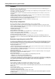
AC Input
Sixpack
component
Input rectifier Sixpack
i1
U1
U2
U3
T
D
i2
i3
Vout
THDI < 3 %
PF > 0.998
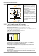
Fig. 4 a-b. Three-phase rectifier with sixpack IGBT modules, drawing sinusoidal current.
Characteristics
High input performance
THDI < 3% (total distortion of the input current)
PF > 0.99 (input power factor)
System design and the above performance levels ensure:
Complete freedom for the installation, no precautions required due to the lack of upstream harmonics.
No harmonic filtering is required.
Total compatibility with gensets, even at low percent loads.
Reduced RMS current (up to 20%) due to optimum sizing of the upstream transformer and cables.
Input protection using ultra-fast fuses
The rectifier input is protected by ultra-fast fuses:
125 A for 20 to 60 kVA, with a breaking capacity of 20 kA
315 A for 80 to 120 kVA, with a breaking capacity of 30 kA.
Input-current limiting
There are no in-rush currents. The rectifier starts with a 10-second walk-in.
Input-current limiting during genset start
This function is particularly useful in installations where the margin between the power rating of the genset and
the UPS is low.
It gradually increases the power drawn on the genset for ten seconds, thus enabling generators equipped with
a turbo to ramp up and supply the full rated load. During the 10-second period, the battery supplies part of the
necessary energy, using the charger as a chopper to step-up the voltage.
2.3 Charger
Operating principle
The charger is supplied by the 800 V DC bus of the PFC rectifier. It supplies the battery charge or float voltage
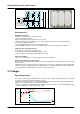
according to a float mode with two charge phases (fig. 5).
First, a constant current equal to 0.1 x IC10 until reaching an end-of-charge float voltage (sealed lead-acid
batteries) or an equalising voltage (vented lead-acid batteries).
Then a constant float or equalising voltage to maintain a slight overcharge. The current gradually drops until
reaching a residual level of approximately IC10 / 5000.
V
oltageU
U
Current I
Charge time t
I
C10
5000
0.1 C10
Float voltage
Float current =
Charge
Charge maintenance
Equalising voltage
Fig. 5. Battery recharge in float mode.