
Specifications


Galaxy 5000 technical specifications
MGE UPS SYSTEMS SPTC5 500 UK – 09/2005 page
24
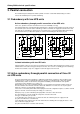
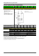
> 250 mm
7
1
0
m
m
> 1000 mm
Fig. 21. No major constraints on installation.
Fig. 22. Installation with separate battery cabinets.
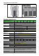
Electrical characteristics
Power rating Pn (kVA at PF = 0.8)
(rated apparent output power)
20 30 40 60 80 100 120
Active power (kW) 16 24 32 48 64 80 96
Input (rated values and tolerances)
Number of phases 3ph + N or 3ph (for operation without neutral)
Normal AC input Un = 400 V
(1)
± 15% i.e. 340 to 470 V at Pn and 250 V to 470 V at 70% Pn (except with
backfeed)
Voltage
Bypass AC input 400 V
(1)
± 10% or ± 15% (option)
Frequency Utility 50 or 60 Hz ± 10% i.e. 45 to 65 Hz
Power factor 50% Pn 0.999 0.992
75 to 100% Pn 0.999 0.998
THDI
(2)
< 3% at Pn, < 5% from 25 to 75% Pn
Max. upstream short-circuit power 20 kA (input protected by 125 A fuses) 30 kA (protected by 125 A fuses)
Currents See the "input and output currents" table below
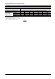
Output (rated values and tolerances)
Number of phases 3 + N or 3ph (for operation without neutral)
Voltage
(rated rms output
value)
380 / 400 / 415 V ± 1% 3-phase at 50 Hz
380 / 400 ± 1% 3-phase at 60 Hz
Fine adjustment possible via user-machine interface to Un ± 3%
AC power sync 50 or 60 Hz ± 0.5 Hz (adjustable) Frequency
free running ± 0.25 Hz (adjustable from 0.25 to 2 Hz in 0.25 Hz steps)
Power factor 0.8 for inductive and resistive loads - 0.9 on capacitive loads
linear load
≤ 1% ph/ph, ≤ 1.5% ph/N (RL loads at cos ϕ = 0.8 and 0.9)
THDU
(3)
non-linear load
≤ 2% ph/ph, ≤ 3.5% ph/N (RCD loads as per standard ENV 50091-3)
Short-circuit capacity of inverter 2.7 In peak for 150 ms
(4)
Overload capacity of inverter 125% for 10 min. - 150% for 1 min. - 220% for 1s
Overload capacity of bypass (SS) Ipeak / In for 20 ms
(4)
– see values below
Single UPS unit 45 29 22 15 29 23 19 (of static switch SS)
Parallel config. 117 77 58 39 38 30 25
Permissible crest factor Up to 3 : 1
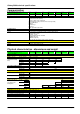
Dynamic performance: voltage transients
during load step changes
± 2% on 0 to 100% or 100 to 0% load step changes
recovery time (return to ± 1%) < 100 ms
Voltage and phase imbalance 1.5% and 2 degrees for 50% current imbalance ???
Maximum frequency variation 1 Hz/s or 2 Hz/s (adjustable)
Efficiency
100% Up to 94% for linear loads and 92% for non-linear loads On-line mode
50% Up to 92% for linear and non-linear loads
ECO mode 100% Up to 97%
Conditions for transfer without interruption between normal and bypass lines
Bypass source voltage tolerances Un ± 10% before bypass to normal transfer
Un - 20% to + 15% after bypass to normal transfer (load supplied by inverter)
Bypass source frequency tolerances ± 8% of 50 or 60 Hz as standard
adjustable to ± 0.5% ± 1%, ± 2%, ± 4%, ± 8%
Phase difference tolerances 3 degrees
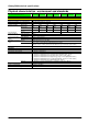
Transfer with interruption
(bypass source outside tolerances)
If any parameter is outside tolerances, transfer can be carried out with an adjustable
interruption of 13 ms to 1 s, after authorisation by the user via the operator keypad