
Specifications
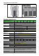

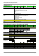
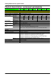


Galaxy 5000 technical specifications
MGE UPS SYSTEMS SPTC5 500 UK – 09/2005 page
21
N
o
r
ma
l
AC input
Load
B
ypas
s
AC input
P1(kVA)P1(kVA) P1(kVA)
ASI3
Réseau
AC by-pass
ASI2
COFFRET BYPASS EXTERNE
ASI1
Réseau
AC normal
Réseau
AC normal
Réseau
AC normal
Utilisation
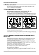
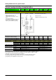
Fig. 17. Manual bypass for a single-
UPS unit.
Fig. 18. Bypass for a parallel UPS system (higher power rating) with a common
bypass AC source.
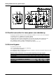
3.3 Parallel connection for more power (no redundancy)
For this type of parallel connection, up to six UPS units are added to cover the needs of the installation:
at least two units, i.e. a minimum of 2 x 20 kVA = 40 kVA
up to six units, i.e. a maximum of 4 x 120 kVA = 480 kVA.
The UPS units share the entire load. Shutdown of one unit stops the entire UPS system because the
remaining units are not sufficient to supply the load (e.g. three 30 kVA units for a 70 kVA load).
This configuration requires a common external bypass for all units.
The general idea is presented in figure 17, but with a load rated 2 P1 < P < 3 P1.
3.4 External bypass
For parallel connection with:
2, 3 or 4 UPS units for more power (no redundancy)
3 or 4 UPS units with redundancy
the configuration requires a common external bypass for all units, sized for the total power rating of the units.
The characteristics are presented below.
Maximum number of UPS units connected in parallel, depending on the type of bypass
Rated power (kVA) of each unit 20 30 40 60 80 100 120
150 kVA enclosure 4 4 3 2 1 1 1
360 kVA cubicle 4 4 4 4 4 3 3
600 kVA cubicle 4 4 4 4 4 4 4
Dimensions (mm) and weight (kg) of the bypass H W D Weight
150 kVA enclosure 1000 800 303 71
360 kVA cubicle 1900 715 825 190
600 kVA cubicle 1900 1015 825 280