
Specifications


Galaxy 5000 technical specifications
MGE UPS SYSTEMS SPTC5 500 UK – 09/2005 page
16
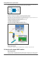
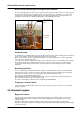
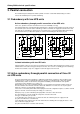
Direct thermal monitoring of the sixpack IGBT modules
A sensor placed directly on the base of the rectifier and inverter sixpack modules monitors the cooling system.
This allows an early detection of a malfunction that, so far, could have been destructive. (i.e. : body on the
heatsink). Then, the UPS transfers without a break to the bypass AC input and sends an alarm to the user.
Avoiding the component to be damaged greatly improves the availability of the UPS.
Sensor on base of
sixpack IGBT
module.
Sixpack IGBT
components
Fig. 12. Direct thermal monitoring of the sixpack IGBT modules.
Cold-start mode
A standard function of Galaxy 5000 is the cold-start mode where the UPS starts on battery power if normal AC
power is not available. This mode is initiated by buttons on the control panel.
Once started, the UPS operates on battery power until the end of the backup time or on genset power that
comes on line to replace the AC power.
This start mode is possible only when the UPS has been started at least once on normal AC power to charge
the chemical capacitors of the DC bus. Subsequently, as long as the control electronics remain supplied
(sleep mode) and the battery circuit breaker is closed, the UPS can start on battery power (if not already
depleted).
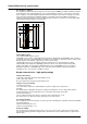
Backfeed protection
There is sufficient space in Galaxy 5000 for two, optional, electromechanical contactors on the normal and
bypass AC lines. These contactors cut the lines upstream of the UPS if AC power fails. This avoids voltage
backfeed on the AC lines if one or more SCRs in the static switches fault (short-circuit).
The contactors are supplied directly by the lines.
With the backfeed option, the permissible input voltage on the normal AC input is between 342 and 470 V.
This restriction is due to the coil of the contactor used.
This option is mandatory for UPSs that must comply with standard EN60950.
Frequency-converter option
Single-UPS units in the Galaxy 5000 range can be used as frequency converters. In this case, the manual
bypass is disabled.
2.6 Automatic bypass
Bypass AC source
The bypass AC source supplies the bypass AC input, generally via a three-phase outgoer + N in the low-
voltage switchboard upstream, separate from the outgoer supplying the normal AC input. It can operate
without a neutral.
However, both AC inputs (normal and bypass) can be supplied by the same outgoer (second cable).
Operation on the bypass AC input is a downgraded mode (except in ECO mode) indicated by an orange LED
on the control panel.